
Appendix C - Editing Road Network Data for Use in LifeSim
The road network is an important part of the LifeSim computations when simulating the evacuation process. A road network with missing connectivity or incorrect directions on one-way roads can lead to erroneous results. This appendix provides some methods for editing the road network dataset to provide a reliable foundation for traffic simulation. This appendix makes use of the editing functionality in the map window of the LifeSim main window. The map window functionality and a full list of the tools available can be found in Appendix B. The base road network used in the following examples was obtained from OpenStreetMap.
This appendix focuses on two aspects of road network improvement:
- Verifying network connectivity.
- Verifying one-way street direction.
Overview
The road network connectivity defines how vehicles can traverse from one road segment to the next road segment in LifeSim. Roads are considered connected if the individual road segments share an end point.
If two roads do not share an end point, then a vehicle within the simulation cannot move between the two roads. Conversely, if two roads share an end point, a vehicle can move between the roads even if one is a bridge and the other is the road going underneath.
The first step is to check for disconnect between road segments: refer to Disconnect Invalid Road Segment Connections and Roads That Should Be Connected.
Another step is to verify the direction on one-way streets: refer to Verify One-Way Street Direction.
Disconnect Invalid Road Segment Connections
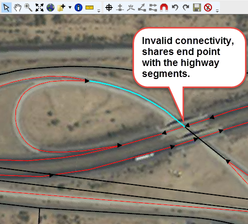
Invalid road segment connections can occur several ways. For example, it is common for overpasses or underpasses to have roads connected at the overpass intersection. In LifeSim, this connection would imply that vehicles can jump from an overpass down onto a highway as if it were a standard intersection.
In Figure, an off-ramp that goes underneath a highway is displayed. The road segment that goes underneath the highway shares an endpoint with the highway. The invalid road segment connection would allow vehicles to immediately jump from the highway to the underpass rather than take the off ramp, which would affect simulation results (i.e., destination arrival times, evacuation times, evacuation outflow).
The following steps can be used to fix road network connectivity issues:
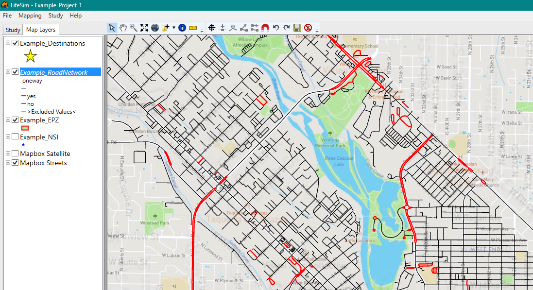
- To display a road network layer to the map window, from the Study tab, from the Road Networks folder, right-click on a road network dataset. From the shortcut menu, click Show In Map Window (Figure).
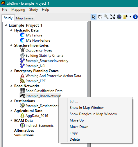
Figure: LifeSim Main Window - Study Tab - Road Networks - Shortcut Menu Options - To start an edit session, from the Map Layers tab on the LifeSim main window, right-click on the road network map layer. From the shortcut menu, click Edit. The selected map layer is now in an active editing session, and the Editor Toolbar is active (Figure)
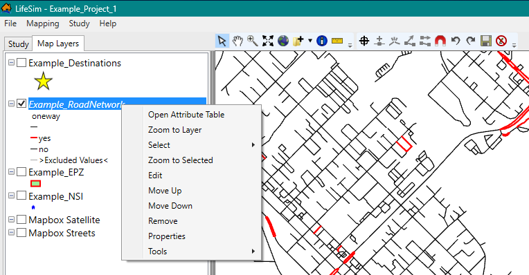
Figure: Map Layer Tab - Example Road Network - Shortcut Menu Options - Enable snapping to ensure the road segment edits connect to the correct map layer. From the Editor Toolbar, click
 . From the Snapping window (Figure), click Enable Snapping. From the Snap To Layer list, select the road network that is currently being edited (e.g., Example_RoadNetwork). Select applicable lines to connect to (e.g., All Points).
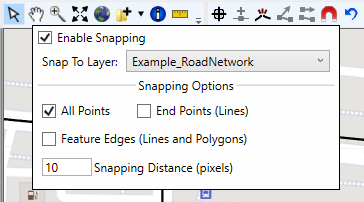
Figure: Edit a Road Network - Enable Snapping - In the Figure example, vehicles traveling east on the Boise Connector highway will incorrectly turn left on the N Orchard St inside-road. To disconnect the invalid connection, use the Break line feature... (K)
 tool to break the connected line segment away from the highway segment.
Now select the segment that shares an end point with the highway segment using the Select tool , and delete the selected segment. Either right-click on the segment and from the shortcut menu, click Delete Selected Features (Figure), or press Delete key.
Next, click and drag the highway segment away from the N Orchard St inside-road and connect to the Boise Connector highway.
Figure: Example: Disconnect Invalid Road Segment Connection with Highway - Now, the road segment does not share an end point with the highway road segments and in LifeSim, vehicles will have to, appropriately, continue east on the highway.
- This process should be repeated for any other roads in the road network that should not be connected.
- Remember to save often (select the Save Edits (Ctrl+S)
 tool) to avoid spending an hour editing the road network and get surprised with a computer restart, or worse, an unexpected error in the software.
Roads That Should Be Connected
Road segments that represent a continuous road can sometimes lack a common endpoint (Figure). When this happens, vehicles in LifeSim cannot move from one segment to the next when in reality the vehicles clearly should be able move freely.
The following steps can be used to fix the connectivity issue:
- A tool that can aid in finding connectivity issues is to display dangles. Dangles display all end points of line segments. From the LifeSim main window, from the Study tab, from the Road Networks folder, right-click on a road network dataset. From the shortcut menu, click Show Dangles in Map Window. A shapefile that contains dangle locations will be generated and displayed in the map window of the LifeSim main window (Figure).
Figure: Road Network Dataset - Show Dangles in Map Window - Dangles Generated and Displayed - To connect the road segment, begin an edit session. From the Map Layers tab on the LifeSim main window, right-click on the road network map layer. From the shortcut menu, click Edit. The selected map layer is now in an active editing session, and the Editor Toolbar is active (Figure).
- Enable snapping to ensure the road segment connects to the correct map layer. From the Editor Toolbar, click. From the Snapping window (Figure), click Enable Snapping. From the Snap To Layer list, select the road network that is currently being edited (e.g., Example_RoadNetwork). Select applicable lines to connect to (e.g., All Points).
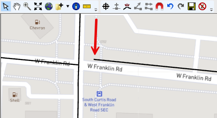
- From the General Toolbar, click the Select tool. Double-click the road segment that is not connected to the intersection to enter vertex editing mode. Click and drag the end point to the vertex desired to connect to. Once close enough, the indicator line will "snap" to the end point of the intersection. Release the left-click to finish moving the vertex. Either left-click away from the line segment or right-click and click Finish Editing Vertices from the shortcut menu to exit the editing session (Figure).
Figure: Connect Road Segments – Better Network Connectivity - Now, the road segment that was previously disconnected will now allow traffic to continue on W Franklin Rd.
- This process should be repeated for any other roads in the road network that should be connected.
- Remember to save often (select the Save Edits (Ctrl+S) tool) to avoid spending an hour editing the road network and get surprised with a computer restart, or worse, an unexpected error in the software.
Verify One-Way Street Direction
LifeSim's traffic simulation engine allows road segments to either be one-way or two-way road segments. If a road is considered one-way, then vehicles can only travel in one direction along the road segment. The direction is defined from the first point in the road segment to the last point in the road segment and can be defined by enabling arrows to be drawn at the end of one-way roads through the road network map layer properties. For details on how to use the map layer properties, refer to Map Layers Properties.
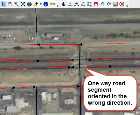
Sometimes a road segment that is defined as one-way will be pointing in the wrong direction. This would mean that vehicles would have to find a way around the incorrectly oriented one-way segment. The following example (Figure) shows a case where a one-way highway segment is pointing in the wrong direction and needs to be fixed.
To fix the orientation of a one-way road segment pointing in the wrong direction, follow the steps below:
- To aid in identifying road segments that may be pointing in the wrong direction, enable arrows to display the direction of the road segment. From the Map Layers tab on the LifeSim main window, right-click on the road network map layer. From the shortcut menu, click Properties (Figure). Select the category of the line to be edited (e.g., this example is a one-way road. Therefore, the yes category of the oneway attribute is selected). Enable the Draw End Arrow checkbox
 (Figure).
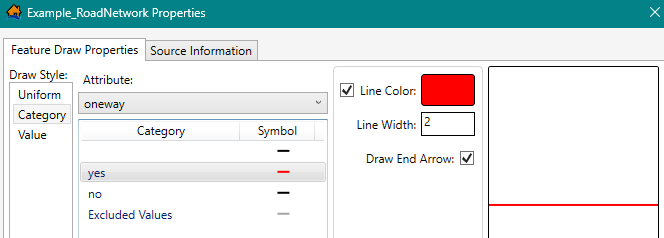
Figure: Map Layer Properties – One-Way Road Segment - Draw End Arrow - To fix the road segment, begin an edit session. From the Map Layers tab on the LifeSim main window, right-click on the road network map layer. From the shortcut menu, click Edit. The selected map layer is now in an active editing session, and the Editor Toolbar is active (Figure).
- From the General Toolbar, click the Select tool. Select the road segment that is oriented in the wrong direction. With the correct segment selected, either press the R key, or right-click, and from the shortcut menu, click Reverse Selected Features (Figure) to reverse the direction of the line segment.
NOTE: Reversing the direction of selected features applies to all features that are currently selected. Make sure that selected line features only contain lines whose direction is desired to be reversed.
Figure: Example: Reverse Selected Features – Shortcut Menu - Now, the one-way road segment that was previously oriented in the wrong direction (against the flow of traffic) will allow traffic to continue in the appropriate direction.
- This process should be repeated for any other roads in the road network that are defined as one-way roads and are oriented in the wrong direction.
- Remember to save often (select the Save Edits (Ctrl+S) tool) to avoid spending an hour editing the road network and get surprised with a computer restart, or worse, an unexpected error in the software.