
Structure Inventories
The next step after adding hydraulic data to the study is to add structure inventories. A structure inventory represents geospatial points that contain damageable elements (typically a structure such as a home). Structure inventories are required and allow LifeSim to estimate direct economic damage for a flood event. To estimate life loss for an event, a structure inventory must be supplied with population data.
Structure occupancy types provide a level of aggregation for structures in LifeSim and are imperative for any consequence calculation. The occupancy types describe depth-damage relationships, life loss parameters, general information about the structures, and contain information about uncertainty computations associated with the structure inventory. Each structure is required to have an occupancy type.
LifeSim Version 2.0 and later can accept structure inventories in the form of point shapefiles and the National Structure Inventory database (NSI) (USACE, n.d.) [?]. This chapter describes the ways structure inventories in different formats can be added to, edited, and displayed in a LifeSim study.
Import from Shapefile
The point shapefile that represents a structure inventory for an area will contain information on structure occupancy types (Appendix C), population, structure values, foundation height, construction type, and other information. The LifeSim Version 2.0 Technical Reference Manual, Chapter 4, provides the definitions for the attributes required for importing a structure inventory from a shapefile.
To create a structure inventory from a point shapefile:
- From the LifeSim main window, from the Study tab, from the Study Tree, right-click on Structure Inventories. From the shortcut menu, click Import Structures From Shapefile (Figure). Another way is from the LifeSim main window, from the Study menu, point to Structure Inventories, click Import Structures From Shapefile (Figure).
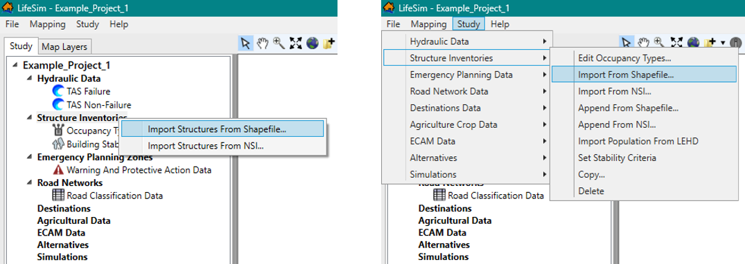
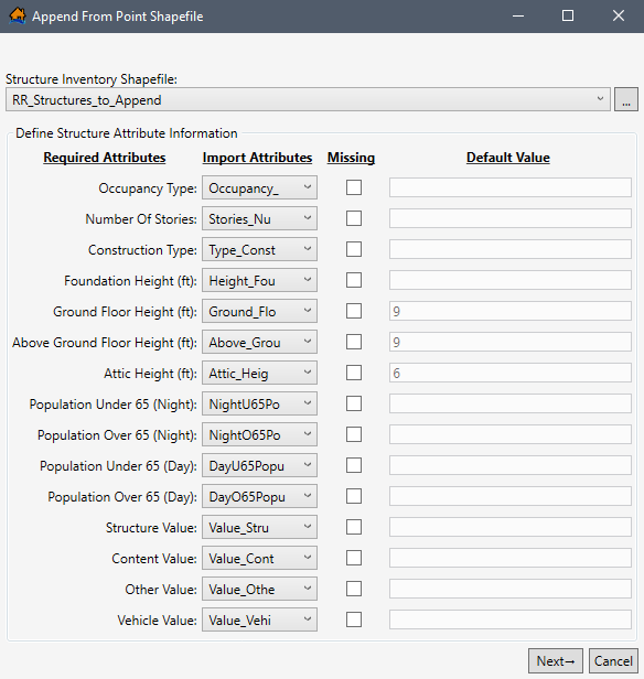
Figure: Import Structures From Shapefile - Study Tree Shortcut Menu (left) and Study Menu Bar (right) - Either way, the Import From Point Shapefile dialog box (Figure) will open.
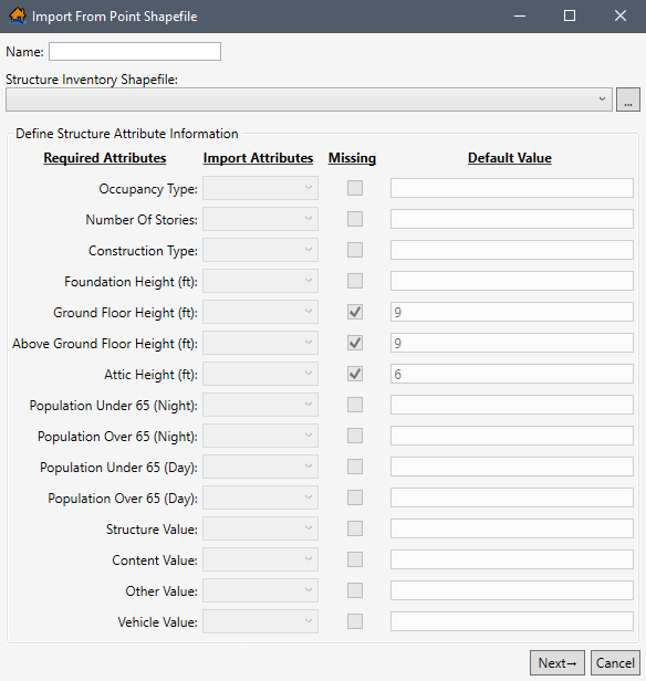
Figure: Import From Point Shapefile Dialog Box - In the Name box, enter a name for the structure inventory.
- To select the shapefile that contains information about the structure inventory, to the right of the Structure Inventory Shapefile dropdown menu (Figure), click
 . An Open browser (Figure) opens. Navigate to the directory where the point shapefile is located. Select the correct point shapefile (e.g., *.shp), click Open, the Open browser will close, and the user will be returned to the Import From Point Shapefile dialog box (Figure). Alternatively, if the desired shapefile has already been imported as a map layer into the LifeSim study, then from the Structure Inventory Shapefile dropdown menu, select the desired map layer.
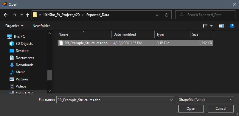
Figure: Open Browser - The Structure Inventory Shapefile box will now contain the name and location of the selected point shapefile (Figure).
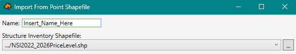
Figure: Import From Point Shapefile - Structure Inventory Shapefile Selected - A structure inventory has required attributes that will be used in a LifeSim study, so the user must provide information about those attributes in the selected point shapefile. From the Import Attributes column (Figure), for each listed Required Attribute, the user must select from a list the field name of the attribute in the selected point shapefile.
- For example, in Figure for Occupancy Type (required attribute), from the Import Attributes list, possible field names are presented for the user. To set the Import Attributes, use the dropdown menu to select the appropriate field name – e.g., occtype in Figure.
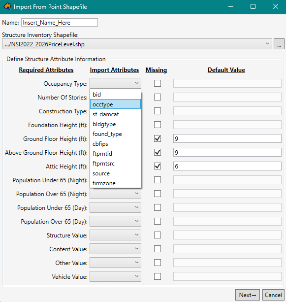
Figure: Define Structure Attribute Information – Occupancy Type
- Text data types will auto populate in Required Attributes that require strings (e.g., occtype for Occupancy Type in Figure), while numeric data types will auto populate in Required Attributes that require number values (e.g., different attributes populated for Foundation Height in Figure).
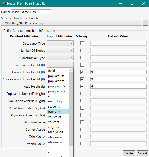
Figure: Define Structure Attribute Information – Foundation Height (Numerical Attribute) - If the point shapefile does not contain a required attribute, the user must click the Missing column's checkbox
 for that required attribute (e.g., Ground Floor Height checked in Figure). In the Default Value column for that required attribute, the value box activates, and the user must enter a value for the required attribute (e.g., 9 in Figure). The user's defined default value will then be applied to all structures in the inventory.
 - Once all of the required structure attribute information has been completed, from the Import From Point Shapefile dialog box, click Next.
Default Occupancy Type Assignments
Next the user must confirm the occupancy type names from the structure shapefile associated with the occupancy type IDs that have been defined in the study. Occupancy types are another level of aggregation for structures. Occupancy types are imperative for the consequence calculations. Refer to Occupancy Type Editor for more information on occupancy types.
- From the point shapefile, LifeSim tries to match up the occupancy type names to the occupancy type IDs that exist in the model (Figure). For example, in Figure, under Occupancy Type, the Default Assignment for RES1-1SNB, LifeSim selected selected RES1-1SNB from the existing occupancy types.
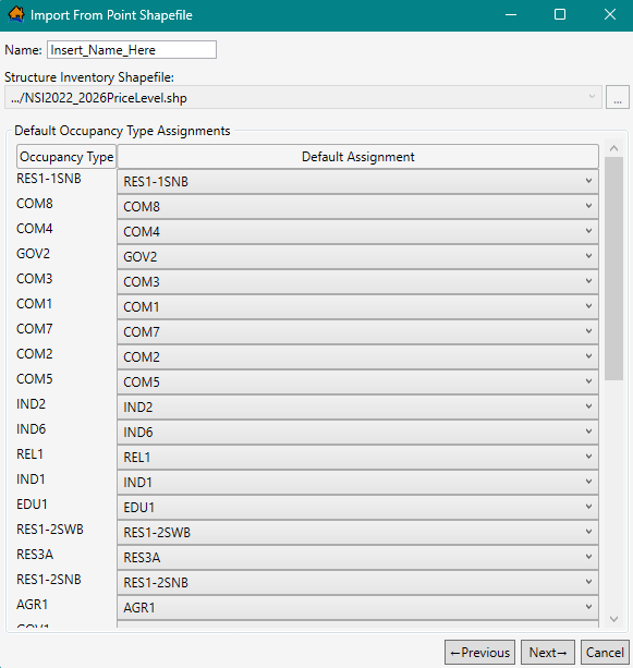
Figure: Default Occupancy Type Assignments - If the default selection is not correct, the user can change the assignment under the Default Assignment dropdown menu (Figure).
Figure: Default Occupancy Type Assignments - Dropdown Menu - If the selected point shapefile does not contain a default occupancy type in the assigned field, then the dropdown menu will be empty. Users can check for different occupancy type names from the Default Assignment dropdown menu (Figure).
- Once the user has reviewed the default occupancy type assignments, from the Import From Point Shapefile dialog box (Figure), click Next.
Stability Criteria Assignments
Next the user must assign structure stability functions. Stability criteria are assigned to a structure based on rules that relate stability functions to identified attribute values. For example, if a rule states that all structures that are construction type ‘Wood’ should be assigned the ‘Wood-Framed Attached’ stability criteria, then once Finish is clicked, every structure that meets the criteria will be assigned the Wood-Framed Attached stability function. These rules are not retained for future use. They are a one-time application to define the stability criteria that will be used by structures. The assigned stability criteria can be viewed through the structure inventory's attribute table (see View a Structure Inventory). Refer to Building Stability Curve Editor for further discussion on structure stability criteria.
LifeSim Version 2.0 and later has default rules that assign stability criteria for structures with specific construction and/or occupancy types. Alternatively, the user may edit an existing default rule or create and define a new rule to assign stability criteria to structures based on any of the structure attributes within the selected point shapefile.
NOTE: the created rules are a 'rule stack,' meaning the order in which the criteria are defined is important. If two rules apply to the same structure, then the higher (top) rule will dominate. Users should make certain all structures are covered by the selected/created rules, for missed structures will not have a stability criteria assignment.
To assign default stability criteria:
- LifeSim provides a list of default rules for assigning stability criteria (Figure). For example, in Figure, the Rule List includes Steel Buildings Collapse Criteria. If a default rule in the Rule List is not desired, then the user can remove the rule. Default rules can also be modified.
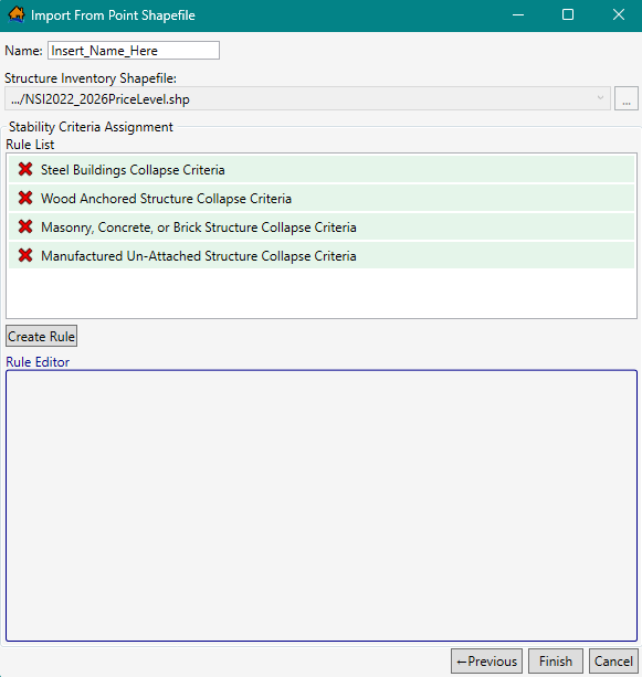
Figure: Default Construction Type Assignments - Default or created rules can be deleted from the Rule List by clicking the Delete
 button next to the name of undesired rule.
- NOTE: to add all default rules removed by accident, (this also removes all rules created by the user), click the Previous button twice to return to the first window in the import wizard (Define Structure Attribute Information window), and then click the Next button twice to return back to the Stability Criteria Assignment window.
- To view the conditions for any rules in the Rule List, select the desired rule (e.g., Manufactured Un-Attached Structure Collapse Criteria) and view the rule conditions in the Rule Editor (Figure).
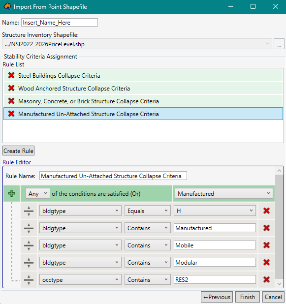
Figure: Import From Point Shapefile – Example Default Rule – Rule Editor - Rules displayed in the Rule Editor (Figure) can be modified. Click the Add
 button to add a new row to the bottom of the rule stack. Click the Delete
button to remove a row. To move a row in the rule stack, click and hold the Move
button to add a new row to the bottom of the rule stack. Click the Delete
button to remove a row. To move a row in the rule stack, click and hold the Move
 button and drag the row to the desired location and drop the row.
 - The first dropdown list in a rule row is populated by the Import Attributes in the selected shapefile (e.g., bldgtype in Figure). The second list contains the appropriate comparison operators (e.g., Equals, Not Equal, and Contains) for the selected Import Attribute. The final list in the row is populated with the selected import attribute fields (e.g., H, Manufactured, ..., RES2).
- To create and define a new Stability Criteria rule, click the Create Rule button. The Rule Editor will populate with the base rule stack (Figure). Enter a name for the new rule in the Rule Name box.
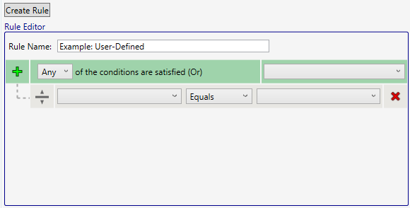
Figure: Import From Point Shapefile – Create New Rule – Rule Editor Example - In the top row, from the dropdown list, select whether the rule is applied if Any or All of the criteria are satisfied. From the rightside dropdown list from the top row, select a construction type from the default list (e.g., Manufactured, Wood-Bouyant - Unknown, etc. in Figure).
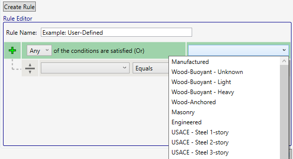
Figure: Import From Point Shapefile – Create New Rule – Construction Type Selection List - Complete the rule definition by adding and defining new conditions for the rule stack. For each row added, select the Import Attribute (e.g., bldgtype in Figure), the comparison operator (e.g., Equals in Figure), and the condition to search for based on the selected Import Attribute (e.g., H in Figure).
- Once the user has the desired stability criteria assignments rules in the Rule List, from the Import From Point Shapefile dialog box, click Finish (Figure).
- The Import From Point Shapefile dialog box will close. From the LifeSim main window, from the Study tab, from the Study Tree, under the Structure Inventories folder, the name of the imported Structure Inventory data set is listed.
Import from National Structure Inventory (NSI)
The National Structure Inventory (NSI) for an area, will contain information on structure occupancy types, population, structure values, foundation height, build type, and other information. The NSI is currently only available to U.S. Army Corps of Engineer (USACE) users. The NSI is a database of structure locations and attributes and was developed using information from the HAZUS database and other sources including the Longitudinal Employer-Household Dynamics database. Technical documentation is available from USACE HEC.
To create a structure inventory from the NSI:
- From the LifeSim main window, from the Study tab, from the Study Tree, right-click on Structure Inventories. From the shortcut menu, click Import Structures From NSI (Figure). Another way is from the LifeSim main window, from the Study menu, point to Structure Inventories, click Import Structures From NSI. Either way, the Import Structures From NSI dialog box (Figure) opens.
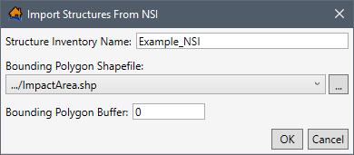
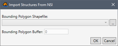
Figure: Import Structures From NSI Dialog Box - In the Structure Inventory Name box, enter a name for the structure inventory (e.g., Example_NSI in Figure).
- To select the bounding polygon shapefile that defines the boundaries of the structure inventory, to the right of the Bounding Polygon Shapefile dropdown menu, click. An Open browser will open (Figure). Navigate to the directory where the bounding polygon shapefile is located. The bounding polygon shapefile must have a projection in order to properly access the NSI database. Select the correct bounding polygon shapefile (e.g., *.shp), click Open, the Open browser will close, and the user will be returned to the Import Structures From NSI dialog box (Figure). Alternatively, if the desired shapefile has already been imported as a map layer into the LifeSim study, then from the Bounding Polygon Shapefile dropdown menu, select the desired map layer.
- In the Bounding Polygon Buffer box, enter a buffer distance for the bounding polygon shapefile (optional). Units are set by the Bounding Polygon Shapefile selection. The default value is zero.
- Click OK. The Import Structures From NSI dialog box will close, and the completed NSI structure download dataset will be added to the Study Tree.
View and Edit a Structure Inventory
An imported structure inventory can be copied or deleted, viewed in the map window, appended with new structures, population information can be imported, and new stability criteria rules can be created.
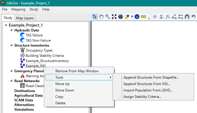
To access the Study Tree shortcut commands and edit an imported structure inventory, from the LifeSim main window, from the Study tab, from the Study Tree, from the Structure Inventories folder, right-click on a structure inventory. The structure inventory shortcut menu opens (Figure). Commands include Show In (or Remove From) Map Window, Tools, Move Up, Move Down, Copy, and Delete. The Tools shortcut submenu (Figure) contain commands for appending the structure inventory, importing population, and adding stability assignment criteria rules.
When a structure inventory is imported, default criteria for damage, stability, and submergence are assigned to structures based on the occupancy type attribute information and the stability criteria rules. The criteria for structure damage, stability, and submergence can be edited, created, and assigned. Occupancy Type Editor and Building Stability Curve Editor describe how to edit the occupancy types and structure inventory criteria, respectively.
Editing individual structures or attributes of the imported structure inventory map layer can be accomplished from the Map Layers tab; review Appendix B for information regarding editing the structure inventory map layer.
View a Structure Inventory
Users can view the structure inventory in the map window and can view the structure inventory attributes.
Show in Map Window
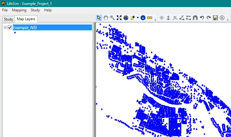
From the LifeSim main window, from the Study tab, from the Study Tree, from the Structure Inventories folder, right-click on a structure inventory. From the shortcut menu (Figure), click Show In Map Window. The selected structure inventory will display in the map window of the LifeSim main window (Figure). Right-click a displayed structure inventory and click Remove From Map Window from the shortcut menu to stop displaying the structure inventory.
View Attributes Table
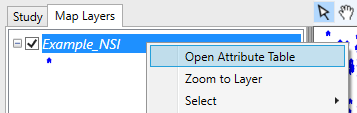
Map layer attributes can be accessed for each map layer and is provided in a table for the dataset referenced by the map layer. The structure inventory dataset must be displayed in the map window before the attribute table can be accessed. To access a specific map layer's attribute table, from the Map Layers tab, right-click on a map layer of interest, and click Open Attribute Table (Figure). The Map Layer Attributes dialog box opens; review Map Layer Attributes Dialog Box for more information. Editing of the map layer attributes is detailed in Editing Map Layer Features and Attributes.
Append Structures
Structures can be appended to from a point shapefile or from NSI.
Append from a Shapefile
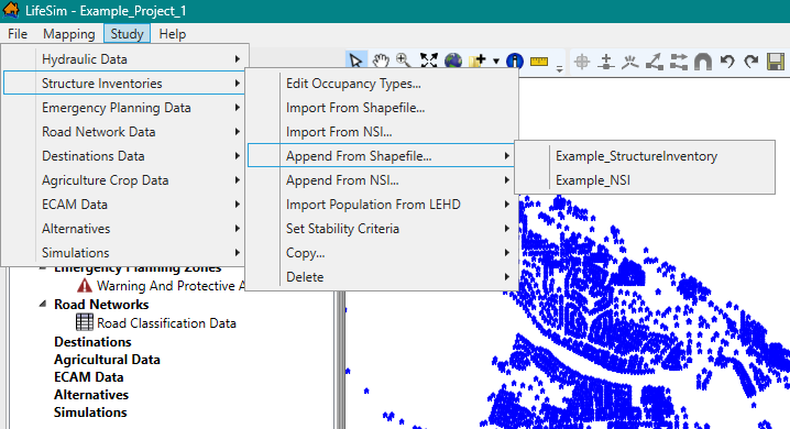
To append the structure inventory from a shapefile, from the LifeSim main window, from the Study tab, from the Study Tree, from the Structure Inventories folder, right-click on a structure inventory (e.g., Example_NSI in Figure). From the structure inventory shortcut menu, point to Tools and select Append Structures From Shapefile submenu command. The Append Structures From Shapefile dialog box opens (Figure).
Alternatively, to open the Append Structures From Shapefile dialog box, from the Study menu, point to Structure Inventories, point to Append From Shapefile and select the structure inventory (Figure).
Select the appropriate shapefile and define the structure attribute information, the default occupancy type assignments, and the stability criteria assignment for the point shapefile. Except for adding a name, the Append Structures From Shapefile dialog box requires the same steps as the Import From Point Shapefile dialog box (Figure); refer to Import from Shapefile for detailed instructions on completing the Import From Point Shapefile dialog box.
Append from NSI
Alternatively, users can append structures from NSI. To append the structure inventory from NSI, from the LifeSim main window, from the Study tab, from the Study Tree, from the Structure Inventories folder, right-click on a structure inventory. From the structure inventory shortcut menu, point to Tools and select Append Structures From NSI submenu command (Figure).
Alternatively, to open the Import Structures From NSI dialog box (Figure), from the Study menu, point to Structure Inventories, point to Append From NSI, and select the structure inventory (Figure).
Either way, the Import Structures From NSI dialog box (Figure) opens. Except for adding a name, the Import Structures From NSI dialog box for appending structures requires the same steps as the Import Structures From NSI dialog box (Figure); refer to Import from NSI for detailed instructions on completing the Import Structures From NSI dialog box.
Import Population from LEHD
Users can import population information for a structure inventory from the Longitudinal Employer-Household Dynamics (LEHD) database.
From the LifeSim main window, from the Study tab, from the Study Tree, from the Structure Inventories folder, right-click on a structure inventory (e.g., Example_NSI in Figure). From the structure inventory shortcut menu, point to Tools and select Import Population From LEHD (Figure) submenu command. The Import Population From LEHD dialog box (Figure) opens.
The Import Population From LEHD dialog box contains a table providing two editable columns (Day Households and Night Households) for users to define the household size for each occupancy type. The entered household size is used to distribute the imported population.
NOTE: all household values must be greater than zero. Cells containing a value of zero are highlighted in red as in Figure. Shortcut menu commands provide users with the ability to Add, Insert, and Delete Row(s); Select All; Copy; Copy w/ Headers, and Paste. Open the shortcut menu by right-clicking the row(s) of interest.
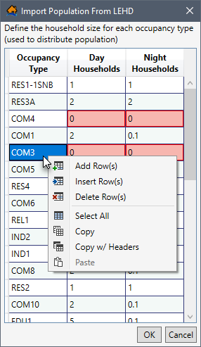
Once the day and night household cells contain the correct household size, click OK to import the population.
NOTE: an error message opens when cells do not contain values greater than zero and the OK button is clicked (Figure).
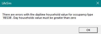
Click OK to close the error message and return to the Import Population From LEHD dialog box (Figure). Fix the cell(s) with zero values, and click OK to import the population.
Assign Stability Criteria
Stability criteria can be assigned to a structure based on rules that relate stability functions to identified attribute values of the structure. The stability criteria assignment tool will take the rules that are defined and use them to assign the selected stability criteria to each structure that meets the rules. For example, if a rule states that all structures that are construction type ‘Wood’ should be assigned the ‘Wood-Framed Attached’ stability criteria, then once OK is clicked, every structure that meets the criteria will be assigned the Wood-Framed Attached stability function. These rules are not retained for future use. They are a one-time application to define the stability criteria that will be used by structures. The assigned stability criteria can be viewed through the structure inventory attribute table (see View a Structure Inventory). Refer to Building Stability Curve Editor for further discussion on structure stability criteria.
Users can create structure inventory specific stability criteria assignment rules from the Stability Criteria Assignment Tool dialog box (Figure). To open the dialog box, from the Study Tree, right-click the structure inventory name. From the shortcut menu, point to Tools, and select Assign Stability Criteria (Figure). The Stability Criteria Assignment Tool dialog box (Figure) opens.
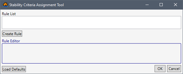
LifeSim Version 2.0 and later has default rules that assign stability criteria for structures with specific construction and/or occupancy types. To load the default rules, click the Load Defaults button. Alternatively, the user may edit an existing default rule or create and define a new rule based on any of the structure attributes within the selected structure inventory.
NOTE: the created rules are a 'rule stack' meaning the order in which the criteria are defined is important. If two rules apply to the same structure, then the higher (top) rule will dominate. Users should make certain all structures are covered by the selected/created rules, for missed structures will not have a stability criteria assignment.
The Import From Point Shapefile dialog box (Figure) requires the same steps as the Stability Criteria Assignment Tool dialog box (Figure); refer to Stability Criteria Assignments for detailed instructions on completing the Stability Criteria Assignment Tool dialog box (Figure).
Copy a Structure Inventory
To copy an existing structure inventory, from the LifeSim main window, from the Study tab, from the Study Tree, from the Structure Inventories folder, right-click on a structure inventory. From the shortcut menu (Figure), click Copy. Another way is from the LifeSim main window, from the Study menu, point to Structure Inventories, point to Copy (Figure), and click on a structure inventory.
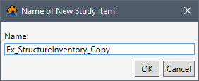
Either way, the Name of New Study Item dialog box (Figure) opens. Enter a new name in the Name box. Click OK, the Name of New Study Item dialog box closes, and the copied structure inventory is added to the Study Tree under the Structure Inventories folder.
Delete a Structure Inventory
To delete an existing structure inventory, from the LifeSim main window, from the Study tab, from the Study Tree, from the Structure Inventories folder, right-click on a structure inventory. From the shortcut menu (Figure), click Delete. Another way is from the LifeSim main window, from the Study menu, point to Structure Inventories, point to Delete (Figure), and click on a structure inventory.
Either way, a Confirm Delete window (Figure) will open asking for confirmation to delete the selected structure inventory.
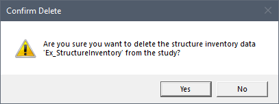
Click Yes, the Confirm Delete message window will close, and the selected structure inventory is deleted. It will no longer display in the Study Tree under the Structure Inventories folder.
Occupancy Type Editor
Each structure is required to have an occupancy type. Occupancy types are a subcategory of the default damage categories assigned to a study and describe a class of structures (e.g., RES1-1SNB is a single family residential structure that is one story tall with no basement). Damage categories represent a high level grouping for structures. They are used in the Economic Consequence Assessment Model (ECAM) process to determine population and capital impacted for each event. In other words, damage categories represent a grouping of occupancy types. By default, a LifeSim study is pre-loaded with default damage categories and occupancy types. Default damage categories are residential, commercial, industrial, and public. Default occupancy types follow the naming convention developed for HAZUS (FEMA 2019) and are listed in the LifeSim Version 2.0 Technical Reference Manual, Appendix D.
Users can modify default occupancy types or create and define new occupancy types with unique depth-damage functions and uncertainty parameters. However, entered data is applied to all the structures assigned to a created or modified occupancy type. Several occupancy types can be assigned to a single damage category. For example, single-story structures with no basements, single-story structures with basements, mobile homes, and duplex apartments are different structure occupancy types assigned to a residential damage category. Structure inventories imported from NSI will automatically have the LifeSim default occupancy types defined as attributes. Structures imported from point shapefiles require users to match the shapefiles occupancy types with the LifeSim preloaded default occupancy type assignment (review Default Occupancy Type Assignments).
Data describing an occupancy type include: the depth-percent damage functions (structure, content, vehicle and other); the evacuation parameters; submergence criteria; and the uncertainties in the first foundation height offset, submergence criteria, variation in values (structure, content vehicle and other) as a percent; and the damage in the depth-damage functions.
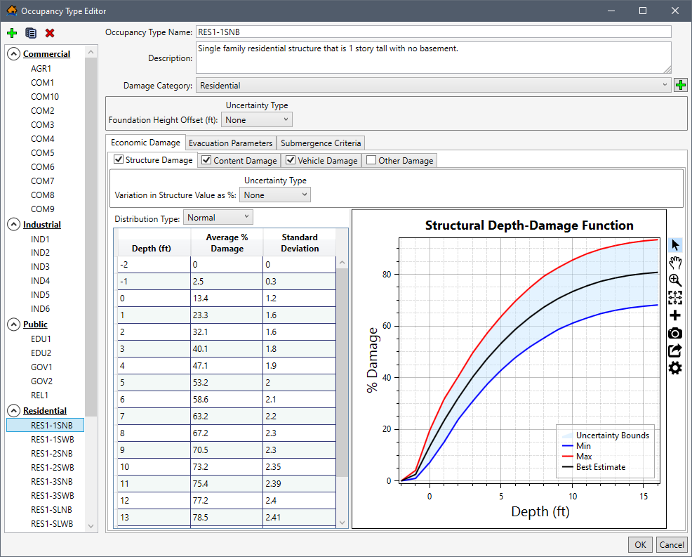
The Occupancy Type Editor (Figure) allows the user to revise and create the evacuation parameters, submergence criteria, economic damage depth-damage functions, value uncertainty, and foundation height uncertainty associated with structures that share common attributes (and therefore grouped by damage category). Also, from the editor, a user can assign damage criteria based on any combination of structure damage category, occupancy class, number of stories, basement information and construction type.
Occupancy Type Editor Structure
To open the Occupancy Type Editor (Figure), from the LifeSim main window, from the Study menu, point to Structure Inventories, and click Edit Occupancy Types (Figure).
Alternatively, from the Study Tree, under Structure Inventories, right-click on Occupancy Types. From the shortcut menu, click Edit Occupancy Type Data (Figure).
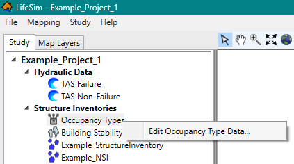
Either way, the Occupancy Type Editor opens (Figure).
Tree
The left side of the Occupancy Type Editor (Figure) provides a view of the occupancy types grouped by damage category in a tree (Occupancy Types Tree). From the Occupancy Types Tree, select an occupancy type name to display the data describing the selected occupancy type. e.g., RES1-1SNB selected in Figure.
Buttons
The Occupancy Type Editor (Figure) has buttons that allow for creating, copying, and deleting of items that are available for a structure occupancy type.
The function of each of the buttons available is listed below:
- Add New Damage Category
 allows allows a user to add a new damage category for grouping occupancy types. Click the Add New Damage Category button, the Name of New Damage Category dialog box opens (Figure). Enter the name for the new damage category in the Name field and click OK to create the new damage category.
NOTE: existing and created damage categories cannot be renamed, copied, or deleted.
Figure: Name of New Damage Category Dialog Box - Create New Occupancy Type
 allows a user to create a new occupancy types. From the Occupancy Type Editor (Figure), click Create New Occupancy Type button. The Name of New Occupancy Type dialog box (Figure) opens. In the Name box, enter a name for the new occupancy type. Click OK, the Name of New Occupancy Type dialog box will close, and users will return to the Occupancy Type Editor (Figure) with the new occupancy type displayed.
Figure: Name of New Occupancy Type Dialog Box - Copy Selected Occupancy Type
 allows the user to copy an existing occupancy type with a new name. From the Occupancy Type Editor (Figure), select an occupancy type from the Occupancy Types Tree list. Click Copy Selected Occupancy Type . The Name of New Occupancy Type dialog will open (Figure). Enter a new name in the Name box. Click OK, and the Name of New Occupancy Type dialog box will close. Users will return to the Occupancy Type Editor (Figure) with the new occupancy type displayed.
Figure: Name of New Occupancy Type Dialog Box - Delete Selected Occupancy Type
 button allows the user to delete the selected occupancy types. From the Occupancy Type Editor (Figure), select an occupancy type from the Occupancy Types Tree list. Click the Delete Selected Occupancy Type button and, a Confirm Delete popup box will appear (Figure). Select Yes to delete an occupancy type, and the selected occupancy type is deleted.
NOTE: this action cannot be undone.
Figure: Occupancy Type Editor - Occupancy Types Tree - Confirm Delete Popup Box - Select the
 button to collapse the damage category group in the Occupancy Types Tree. Clicking the collapse icon hides the damage category groups. And vice versa: select the
  to expand the damage category group and view the list of occupancy types (Figure).
Figure: Occupancy Type Editor - Occupancy Types Tree - Expand or Collapse Damage Category Groups
Occupancy Type Data
From the Occupancy Type Editor (Figure), the right side of the editor contains the data entered for the selected occupancy type (e.g., RES1-1SNB in Figure). Directly below the Occupancy Type Name field is the Description field; both fields can be edited. Modify or set the damage category for selected occupancy type using the Damage Category dropdown menu; the menu contains the list of default damage categories (and any user added damage categories). Edit or set the uncertainty in the foundation height offset from the Foundation Height Offset panel. Add or edit the structure, content, vehicle, and other depth-damage functions from the set of tabs located within the Economic Damage tab; set the warning and protective action behavior from the Evacuation Parameters tab; and set the uncertainty in the high hazard heights from the Submergence Criteria tab. Review the next section to learn how to create and define a new occupancy type in the Occupancy Type Editor (Figure).
Create or Edit an Occupancy Type
The following sections describe how to create a new occupancy type and define the individual components of the occupancy type.
NOTE: skip the instructions for creating a new occupancy type and start from the damage category assignment section to learn how to editing an existing or copied occupancy type.
Create New Occupancy Type
To open the Occupancy Type Editor (Figure), from the LifeSim main window, from the Study menu, point to Structure Inventories, and click Edit Occupancy Types (Figure). Alternatively, from the Study Tree, under Structure Inventories, right-click on Occupancy Types. From the shortcut menu, click Edit Occupancy Type Data (Figure).
- From the Occupancy Type Editor (Figure), click Create New Occupancy Type button. The Name of New Occupancy Type dialog box (Figure) opens.
- In the Name box, enter a name for the new occupancy type. Click OK, the Name of New Occupancy Type dialog box will close, and users will return to the Occupancy Type Editor (Figure) with the new undefined occupancy type displayed.
Assign the Damage Category
By default, newly created occupancy types are added alphabetically to the occupancy type list for the damage category selected at the time that the new occupancy type was created. For example, if the user has AGR1 occupancy type name selected (in the Occupancy Types Tree) and creates the new occupancy type, then the new occupancy type will automatically be added to the Commercial damage category (Figure). Select the appropriate damage category from the Damage Category dropdown menu (Figure). Alternatively, create an new damage category by clicking the Add New Damage Category
button to open the Name of New Damage Category dialog box (Figure). Enter the name for the new damage category in the Name field and click OK to create the new damage category.
NOTE: existing and created damage categories cannot be renamed, copied, or deleted.Enter the Foundation Height Offset
The user can set or modify the uncertainty around the foundation height using the Foundation Height Offset. The user needs to define the uncertainty about foundation heights at the occupancy type level using the structure's foundation height attribute as the most likely or mean estimate. For example, if all RES1-1SNB occupancy type structures have uncertainty about foundation height of 1’, then the Foundation Height Offset could be set to a uniform distribution of minimum -1’ and maximum of 1’. The default uncertainty is None. From the Uncertainty Type dropdown menu (Figure), the user can choose Triangular, Normal (standard deviation), and Uniform (minimum, maximum). For the example provided in Figure, Triangular has been selected; therefore, the Minimum and Maximum values need to be entered.

Figure: Foundation Height Offset Uncertainty – Triangular Example Enter the Economic Depth-Damage Functions
The Economic Damage tab holds the Structure Damage, Content Damage, Vehicle Damage, and Other Damage sub-tabs (Figure). Each sub-tab provides the same configuration for entering and defining the depth-damage functions. Therefore, the following instructions -- although written from the perspective of the Structure Damage sub-tab -- can be used to complete any of the depth-percent damage functions (structure, content, vehicle and other). To enter the structure damage depth-damage function, enable the Structure Damage (Figure) sub-tab by checking the
checkbox for the tab.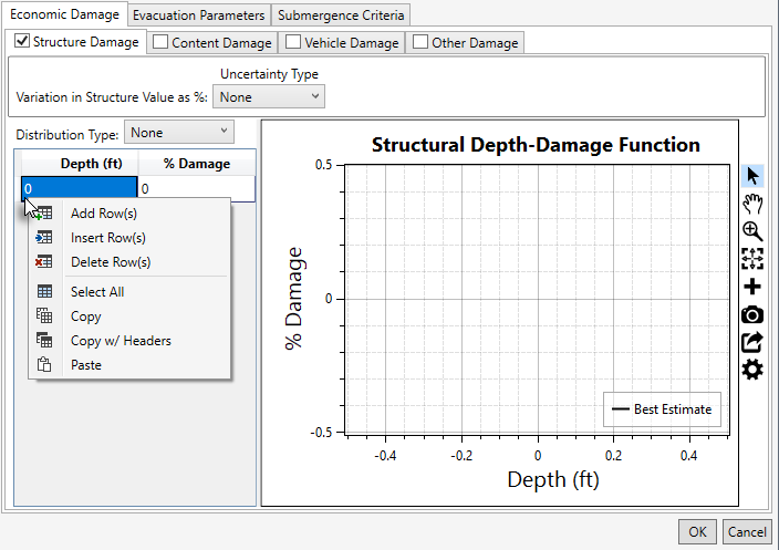
Figure: Occupancy Type Editor – Economic Damage Tab – New Occupancy Type - The user can set the Variation in Structure Value as % (Figure) by defining the uncertainty about the structure value associated with a structure based on the selected occupancy type. From the Uncertainty Type dropdown menu, the default selection is None. The uncertainty types available are the Triangular(minimum, maximum), Normal (standard deviation), and Uniform (minimum, maximum).
- The user can also set the uncertainty associated with how much damage can occur from depths of water at the structure for the Structure Depth-Damage Function (Figure). By default, the uncertainty in the structure depth-damage function is None. Uncertainty types available are the Triangular (minimum, maximum), Normal (standard deviation), and Uniform (minimum, maximum).
- Depth-damage function values can be entered into the Depth-Damage Function Table (Figure) by hand, copied from another occupancy type or from another application (e.g., Microsoft Excel®) and pasted into the table (i.e., entire table, individual cells, columns, rows). From the Depth-Damage Function Table, right-click to open the shortcut menu (Figure). From the shortcut menu, the user can Add, Insert, and Delete Row(s); Select All; Copy; Copy w/ Headers, and Paste. For example, from another occupancy type, select a cell in the table and use Ctrl + A (or right-click and select the Select All command from the shortcut menu) to select the entire table. Use Ctrl + C (or the Copy shortcut menu command) to copy the data to the clipboard. Return to the newly created occupancy type and select the first cell in the first row and use Ctrl + V to paste all the copied data. The depth-damage function table can also be copied (with or without headers) into another application (e.g., Microsoft Excel®) for saving. Use Ctrl + A (or the Select All command from the shortcut menu), right-click and select Copy w/ Headers. Then paste the data in the desired application to save.
- Errors in the depth-damage function are highlighted in red and a tooltip displays a message describing the error (Figure). Right-click on a header row to open the shortcut menu (Figure) to sort the table in ascending or descending order or clear the table sorting. The Structural Depth-Damage Function plot provides a live update for the data entered in the table. Review Customizing Plots and Plotting Tools for instructions on using the general plotting tools (located on the right side of the plot window) and for customizing plots.
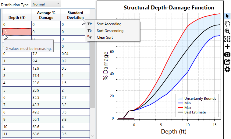
Figure: Example – Occupancy Type Editor – Depth-Damage Function - Complete the economic depth-damage functions by repeating the above steps to enter the content, vehicle, and other depth-damage functions from the Content Damage, Vehicle Damage, and Other Damage sub-tabs (Figure), respectively.
Set the Evacuation Parameters
After completing the economic depth-damage functions for the new occupancy type, select the Evacuation Parameters tab (Figure). This tab contains evacuation parameters set for all structures assigned to the selected occupancy type. Review the LifeSim Technical Reference Manual for more information regarding the evacuation parameters defined by the structure occupancy type.
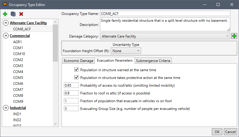
Figure: Occupancy Type Editor – Evacuation Parameters Tab - From the Evacuation Parameters tab (Figure), define the following evacuation parameters for the new occupancy type:
- Population in structure warned at the same time: The user can set warning and protective action behavior for the selected occupancy type. If the Population in structure warned at the same time checkbox is selected, then the warning will reach all people in the structure at once instead of at different times. For example, in an apartment building, residents could receive a warning at different times but for a single family residential structure the warning will reach all people in the structure at the same time.
- Population in structure takes protective action at the same time: The user can also select Population in structure takes protective action at the same time. This is where all of the people within the structure will try to evacuate at the same time. For example, in a single-family residential structure, everyone will try to evacuate at the same time. But in a commercial structure, everyone might try to evacuate at different times.
- Probability of access to roof/attic (omitting limited mobility): Enter the probability that the population of the structure can access the roof or attic of the structure in the Probability of access to roof/attic (omitting limited mobility) field. By default, the probability is set to to 0.9, and the range of possible probabilities is 0.0 to 1.0.
- Fraction to roof vs attic (if access if possible): In the Fraction to roof vs attic (if access if possible) field, set the fraction of the population of the structure that can access the roof. By default, the fraction for roof vs. attic is 1; enter a value between 0.0 and 1.0.
- Fraction of population that evacuate in vehicles vs on foot: For the Fraction of population that evacuate in vehicles vs on foot field, enter the fraction of the structure’s population that evacuate in vehicles vs. on foot. By default, the fraction for vehicle vs. on foot is 1; enter a value between 0.0 and 1.0.
- Evacuating Group Size (e.g., number of people per evacuating vehicle): By default, the Evacuating Group Size (e.g., number of people per evacuating vehicle) field is 3. Enter the appropriate group size for the created occupancy type. For example, RES5 (institutional dormitories) has a set group size of 48 to simulate evacuation by bus.
Enter the Submergence Criteria
Submergence is defined as a water level at a structure that can affect probability of survival. The submergence criteria in LifeSim Version 2.0 and later is used to define the threshold between high hazard and low hazard conditions when people are trapped in a flooded structure.
NOTE: in LifeSim Version 1.0, submergence criteria were divided into three zones: chance, compromise, and safe. However, in LifeSim Version 2.0, the original three zones were replaced with two new zones: low and high hazard. The LifeSim Version 2.0 Technical Reference Manual, Chapter 9, Section 9.2 provides a detailed explanation regarding the development of the two new zones. LifeSim Version 2.0 and later characterizes the high hazard or low hazard conditions as described below:- High Hazard Zone: Refers to those conditions where the stability criteria or submergence criteria of the person, the vehicle (if caught while evacuating), or the structure (if not mobilized) has been exceeded. When the stability (or submergence) criteria has been exceeded, survival depends largely on chance.
- Low Hazard Zone: Refers to those conditions where the person or group of people are exposed to relatively calm floodwaters, where the stability of the individual, group, or shelter is not at risk. A hazard exists due to the potential for bad things to happen when people come in contact with water in locations not meant for such an interaction.
- The threshold of submergence is an uncertain parameter sampled uniquely for each structure. Review the LifeSim Technical Reference Manual for more information regarding the submergence criteria. To enter the submergence criteria for the High Hazard Zone for the new occupancy type, select the Submergence Criteria tab (Figure) and set the uncertainty in the threshold of submergence from the Uncertainty Type dropdown menu. The user can choose Triangular, Normal (standard deviation), and Uniform (minimum, maximum); or select None for no uncertainty. For the example provided in Figure, Triangular has been selected for all three criteria; therefore, the Minimum, Most Likely, and Maximum values need to be entered.
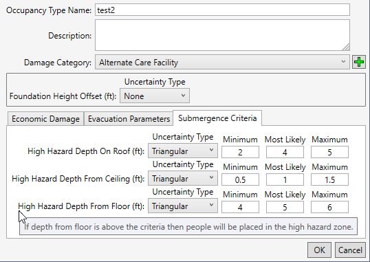
Figure: Occupancy Type Editor – Submergence Criteria Tab – Default Values - Users set the threshold values for the three potential high hazard zones. If the depth of flooding is above the defined high hazard zone, then people caught in the structure will be placed in the high hazard zone. The three submergence criteria are:
- High Hazard Depth On Roof (ft): users set the threshold for this high hazard zone with or without uncertainty by entering depth (ft) as measured from the roof up. For the example provided in Figure, the most likely value (or best estimate) is 4 ft above the roof, with a minimum of 2 ft and maximum of 5 ft above the roof. In this case, if the depth of flooding is above the High Hazard Depth On Roof submergence criteria, then able-bodied people caught on the roof will be placed in the high hazard zone.
- High Hazard Depth From Ceiling (ft): users set the threshold for this high hazard zone with or without uncertainty by entering depth (ft) as measured from the top of the ceiling (of the top floor of the building). For the example provided in Figure, the most likely value (or best estimate) is 1 ft below the ceiling, with a minimum of 0.5 ft and maximum of 1.5 ft below the ceiling. In this case if the depth of flooding is above the High Hazard Depth From Ceiling submergence criteria, then able-bodied people caught in the structure will be placed in the high hazard zone.
- High Hazard Depth From Floor (ft): users set the threshold for this high hazard zone with or without uncertainty by entering depth (ft) as measured from floor towards the ceiling (of the top floor of the building). For the example provided in Figure, the most likely value (or best estimate) is 5 ft above the floor, with a minimum of 4 ft and maximum of 6 ft above the floor. In this case if the depth of flooding is above the High Hazard Depth From Floor submergence criteria, then limited mobility occupants caught in the structure will be placed in the high hazard zone.
- Once information about the selected occupancy type is entered, from the Occupancy Type Editor (Figure), click OK. The Occupancy Type Editor will close, and the information for the new (or edited) occupancy type is saved.
Delete an Occupancy Type
From the Occupancy Type Editor, select an occupancy type from the lefthand list of occupancy types (Figure).
Click the Delete
 button and
a Confirm Delete window opens asking for confirmation to delete the selected item (Figure). Click Yes,
the Confirm Delete message window closes, and the selected stability criteria is deleted.
button and
a Confirm Delete window opens asking for confirmation to delete the selected item (Figure). Click Yes,
the Confirm Delete message window closes, and the selected stability criteria is deleted.
Copy an Occupancy Type
From the Occupancy Type Editor, select an occupancy type from the lefthand list of occupancy types (Figure).
Click Copy  , and
the Save Occupancy Type As (Name of New Occupancy Type) dialog will open (Figure). Enter a new name in the Name box.
Click OK, and the Save Occupancy Type As dialog box will close. Users will return
to the Occupancy Type Editor (Figure) with the new occupancy type displayed.
, and
the Save Occupancy Type As (Name of New Occupancy Type) dialog will open (Figure). Enter a new name in the Name box.
Click OK, and the Save Occupancy Type As dialog box will close. Users will return
to the Occupancy Type Editor (Figure) with the new occupancy type displayed.
Building Stability Curve Editor
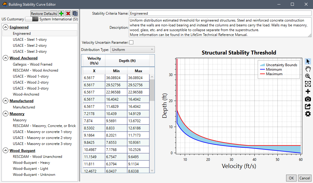
Stability criteria defines the depth and velocity threshold for total structure collapse due to a hazard. The threshold is defined by a depth-velocity curve. If at any time during a simulation the depth and velocity are at a point above the velocity curve, then the structure is assumed to be collapsed -- which can have significant impacts on estimated life loss. The building stability criteria is generally based on the construction type. The user can add, edit, and assign stability criteria based on the structure attributes: construction type, number of stories, occupancy type. The Building Stability Curve Editor (Figure) allows the user to define stability criteria for the structure inventory.
Building Stability Curve Editor Overview
Similar to the Occupancy Type Editor (Figure), the Building Stability Curve Editor (Figure) contains a tree on the left side to allow users to select a building stability criteria from the list of defaults. Selected stability criteria data includes a Structural Stability Threshold plot and is displayed on the right side of the editor. The Structural Stability Threshold plot has a toolbar; review Customizing Plots and Plotting Tools for instructions on using the general plotting tools (located on the right side of the plot window) and for customizing plots. The Building Stability Curve Editor has buttons for creating, deleting and copying a selected stability criteria. The following sections describes the Building Stability Curve Editor in more detail.
Tree
The left side of the Building Stability Curve Editor (Figure) provides a view of the stability criteria grouped by construction type in a tree (Stability Criteria Tree). From the Stability Criteria Tree, select a stability criteria name to display the data describing the selected stability criteria in the right side of the editor.
Buttons
The Building Stability Curve Editor (Figure) has buttons that allow for creating, deleting, and copying
of stability criteria. In addition to the buttons, the Building Stability Curve Editor allows the user to set the display units;
slide the bar to
either US Customary (feet)  or System
International (SI) (meters)
for the desired display units.
or System
International (SI) (meters)
for the desired display units.
The button functions are listed:
- Restore Defaults
 button removes all edits made to the default building stability curves.
NOTE: selecting the Restore Defaults button also removes all custom created stability criteria thresholds. To restore the default building stability criteria, click the Restore Defaults button. The Clear Existing message window (Figure) opens. Click Yes to close the Clear Existing message window and restore defaults. Click No to close the Clear Existing message window and load defaults without removing the existing occupancy types. Click Cancel to close the Clear Existing message window without restoring defaults.
Figure: Clear Existing Message Window - Create New Stability Function allows a user to create a stability criteria. Click the Create New Stability Function button, and the the Name of New Stability Criteria Threshold dialog box (Figure) opens. In Name box, enter a name for the new stability criteria. Click OK, and the Name of New Stability Criteria Threshold dialog box closes. The Building Stability Curve Editor (Figure) displays the new blank stability criteria.
Figure: Name of New Stability Criteria Threshold Dialog Box - Delete Selected Stability Function allows the user to delete selected stability criteria. From the Building Stability Curve Editor (Figure), select a stability criteria from the lefthand list of names. Click Delete Selected Stability Function, and a Confirm Delete window (Figure) opens asking the user for confirmation to delete the selected item. Click Yes to close the Confirm Delete message window and delete the selected stability criteria.
Figure: Confirm Delete Message Window - Copy Selected Stability Function allows the user to copy an existing stability criteria with a new name. From the Building Stability Curve Editor (Figure), select a stability criteria from the lefthand list of names. Click Copy Selected Stability Function, and the Name of New Stability Criteria Threshold dialog box (Figure) opens. By default, the selected stability criteria name is entered in the Name box and appended with “_Copy”. Keep the default name or enter a new name in the Name box. Click OK, and the Name of New Stability Criteria Threshold dialog box closes. The Building Stability Curve Editor (Figure) then displays the copied stability criteria.
Figure: Copy – Name of New Stability Criteria Threshold Dialog Box - Select the button to collapse the construction type group in the Stability Criteria Tree. Clicking the collapse icon hides the construction type groups. And vice versa: select the to expand the construction type group and view the list of stability criterias (Figure).
Figure: Building Stability Curve Editor - Stability Criteria Tree - Expand or Collapse Construction Type Groups
Create or Edit a Building Stability Criteria
To create a new stability criteria:
- To open the Building Stability Curve Editor (Figure), from the LifeSim main window, from the Study Tree, under Structure Inventories, right-click on Building Stability Criteria. From the shortcut menu, click Edit Building Stability Criteria Data... (Figure). The Building Stability Curve Editor (Figure) opens.
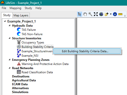
Figure: LifeSim Study Tree – Structure Inventories – Edit Building Stability Criteria Data Shortcut Command - From the Building Stability Curve Editor (Figure), click the Create New button. The Name of New Stability Criteria Threshold dialog box (Figure) opens.
- Enter a name (required) in the Name box for the new stability criteria. Click OK, and the Name of New Stability Criteria Threshold dialog box (Figure) closes. The Building Stability Curve Editor displays the new blank stability criteria (e.g., "Manufactured_ACF" in Figure)
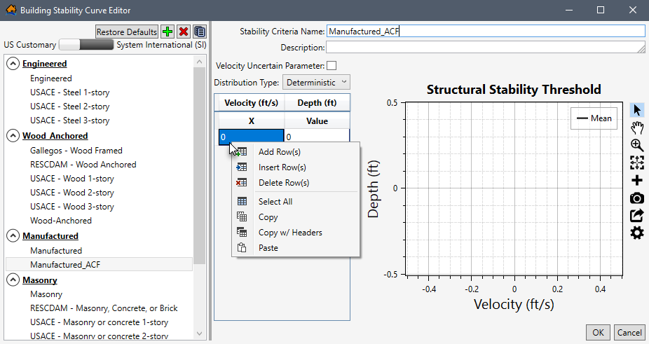
Figure: Building Stability Curve Editor – New Structure Criteria An existing stability criteria can be edited or a newly created criteria can be defined following the remaining instructions in this section.
Enter a description (optional but recommended) in the Description field (Figure).- Next, enter the structural stability threshold curve in the table on the Building Stability Curve Editor (Figure). If adding uncertainty for the depth (ft) parameter, uncheck the
 checkbox to disable the Velocity Uncertain Parameter. By default, the checkbox is unchecked. Alternatively, to add uncertainty for the velocity parameter, check the checkbox to enable the Velocity Uncertain Parameter.
NOTE: Depth (ft) is now the x-variable and Velocity (ft/s) is now the y-variable (Figure).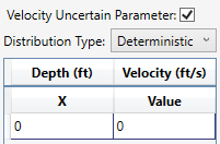
Figure: Velocity Uncertain Parameter Enabled - From the Distribution Type dropdown menu (Figure), select the desired distribution type for the y-variable. By default, Deterministic is selected. The distribution types available are:
- Normal: mean (μ), standard deviation (σ).
- Truncated Normal: mean (μ), standard deviation (σ), minimum, maximum.
- Log-Normal: mean (of log, μ), standard deviation (of log, σ).
- Triangular: minimum (a), most likely (c), maximum (b).
- Uniform: minimum, maximum.
- The threshold depth-velocity curve can be entered into the Structural Stability Threshold table (Figure) by hand, copied from another stability criteria, or from another application (e.g., Microsoft Excel®) and pasted into the table (i.e., entire table, individual cells, columns, rows). From the Structural Stability Threshold table, right-click to open the shortcut menu (Figure). From the shortcut menu, the user can Add, Insert, and Delete Row(s); Select All; Copy or Copy with Headers; and Paste.
For example, from another stability criteria, select a cell in the table and use Ctrl + A (or right-click and select the Select All command from the shortcut menu) to select the entire table. Use Ctrl + C (or the Copy shortcut menu command) to copy the data to the clipboard. Return to the newly created stability criteria and select the first cell in the first row and use Ctrl + V to paste all the copied data.
The stability threshold table can also be copied (with or without headers) into another application (e.g., Microsoft Excel®) for saving. Use Ctrl + A (or the Select All command from the shortcut menu), right-click and select Copy w/ Headers, then paste the data in the desired application to save.
Errors in the stability threshold table are highlighted in red and a tooltip displays a message describing the error (e.g., such as Figure). Right-click on a header row to open the shortcut menu (Figure) to sort the table in ascending or descending order, or clear the table sorting.
The Structural Stability Threshold plot (Figure) provides a live update for the data entered in the table. Review Customizing Plots and Plotting Tools for instructions on using the general plotting tools (located on the right side of the plot window) and for customizing plots. - Click OK (Figure). The Building Stability Curve Editor closes and saves all edits to building stability curves.
Delete a Stability Criteria
To delete an existing stability criteria, from the Building Stability Curve Editor (Figure), select a
stability criteria from the lefthand list of stability criteria names. Click
the Delete button.
A Confirm Delete window (Figure) opens asking for confirmation to delete the
selected item. Click Yes, the Confirm Delete message window closes, and the selected stability criteria is deleted.
Copy a Stability Criteria
To copy an existing stability criteria, from the Building Stability Curve Editor (Figure), select a
stability criteria from the lefthand list of stability criteria names. Click
the Copy button.
The Name of New Stability Criteria Threshold
dialog box opens. By default, the selected stability criteria name is entered in the Name box
and appended with “_Copy” (Figure). Keep the default name or enter a new name in the Name box.
Click OK. The Name of New Stability Criteria Threshold dialog box closes. The Building Stability
Curve Editor (Figure) displays the copied stability criteria.