Alternatives
An alternative in LifeSim allows the user to define what input data sources and parameters will make up the simulation computations. Any combination of input data sources can be used to define an alternative. For example, one alternative may use a road network that allows for contra-flow and another may use a different hydraulic event or different warning issuance times. Setting up multiple alternatives allows the user to quantify and compare the effects of operational changes on the hazard analysis.
Alternatives in LifeSim represent the parameters that define a simulation and include defining:
-
Input data sources (e.g., hydraulics, structure inventory, road network, ECAM data),
-
Warning issuance times,
-
Destination locations by Emergency Planning Zone (EPZ), and
-
Various other parameters (e.g., evacuation parameters, life loss probability, stability criteria).
Create an Alternative
To create an alternative in LifeSim the user will provide a name, define the input data sources, and provide additional information (e.g., evacuation parameters).
- From the LifeSim main window, from the Study tab, from the Study Tree, right-click on Alternatives, and and click Create New Alternative from the shortcut menu (Figure). Alternatively, from the LifeSim main window, from the Study menu, point to Alternatives, and click Create New (Figure).
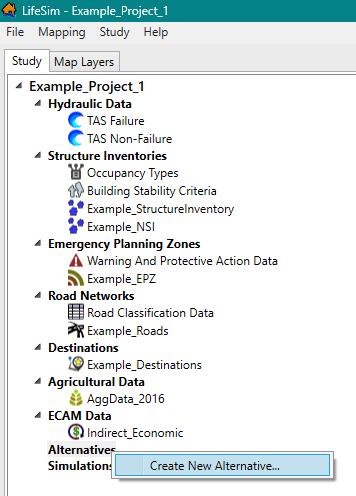
Figure: LifeSim Main Window - Study Tree - Alternatives Shortcut Menu 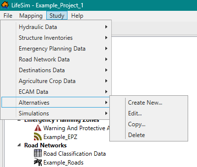
Figure: LifeSim Main Window - Study Menu - Alternatives - Either way, the Create New Alternative dialog box (Figure) opens. Enter a name for the alternative in the Name box.
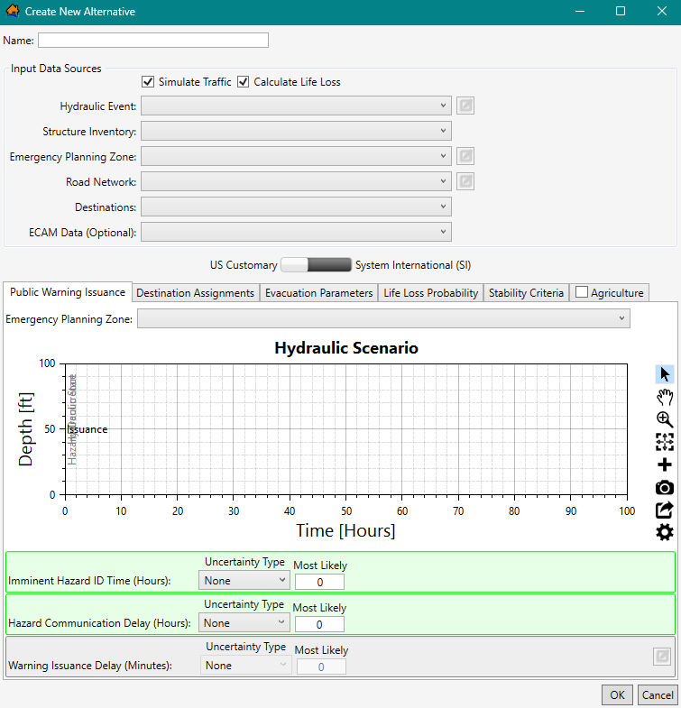
Figure: Create New Alternative Dialog Box
Define Input Data Sources
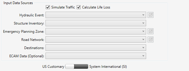
From the Input Data Sources panel (Figure), select the desired simulation compute options and define the desired input datasets for the new alternative.
- By default, LifeSim will create a traffic simulation of the evacuation. To turn off the traffic simulation option, from the Input Data Sources panel, uncheck
 the Simulate Traffic checkbox (Figure).
 - By default, the Calculate Life Loss option is turned on/checked
 . To turn off the life loss calculation option, from the Input Data Sources panel, uncheck the Calculate Life Loss checkbox.
NOTE: If Simulate Traffic and Calculate Life Loss are turned off, then the Road Network and Destinations datasets do not need to be defined. - From the Hydraulic Event list, select a hydraulic dataset. If the selected hydraulic dataset requires editing, click
 . The Select Hydrograph and Timing Information dialog box opens (see Editing, Viewing, and Removing Hydraulic Datasets for further information).
 - From the Structure Inventory list, select a structure inventory.
- From the Emergency Planning Zone list, select an EPZ dataset. If the selected EPZ dataset requires editing, click, and the Emergency Planning Zone Editor opens (see EPZ Editor for further information).
- When simulating traffic (Simulate Traffic checkbox is selected), select the appropriate road network dataset from the Road Network list. If the selected road network dataset requires editing, click , and the Edit Road Network dialog box opens (see Edit a Road Network Dataset for further information).
- When simulating traffic, select the appropriate destinations dataset from the Destinations list.
- Below the Input Data Sources panel, select either US Customary (feet)
 or System International (SI) (meters) for the alternative. The Public Warning Issuance, Destination Assignments, Evacuation Parameters, Life Loss Probability, Stability Criteria, and Agriculture tabs at the bottom half of the Create New Alternative dialog box (Figure) provide the parameters for defining the simulation compute options. The following section (Compute Options for an Alternative) describes the steps for defining the compute options for an alternative for each tab.
 - Click OK, and the Create New Alternative dialog box (Figure) closes. The alternative is created and appears in the Study Tree under Alternatives.
Compute Options for an Alternative
LifeSim can analyze a variety of flood damages and impacts through a variety of computational methods. Flood damages and impacts as well as the methods used to estimate the impacts are selected as part of an alternative definition. For example, when simulating traffic and life loss, users must define warning issuance scenarios, destination assignments, evacuation parameters, life loss probability functions, and stability threshold functions. The following sections describe the steps for defining the compute options for an alternative individually for each tab in the Create New Alternative dialog box (Figure).
NOTE: for the purposes of the discussion the units listed in this section will be in US Customary units (feet). However, the Create New
Alternative dialog box (Figure) allows users to select either US
Customary (feet) or System
International (SI) (meters).
Public Warning Issuance
When simulating life loss, with or without simulating traffic or ECAM, the warning issuance times must be defined. To define the warning issuance scenarios:
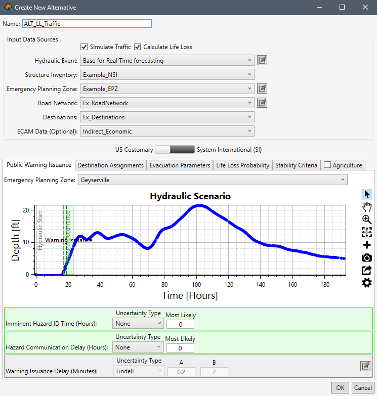
- From the Create New Alternative dialog box (Figure), click the Public Warning Issuance tab.
- The Emergency Planning Zone list within the Public Warning Issuance tab is a list of all the emergency planning zones in the selected Input Data Sources Emergency Planning Zone dataset. Therefore, if a selected EPZ dataset (e.g., Example_EPZ in Figure) has multiple zones, then the list will contain the names of the multiple zones (e.g., Clakamas County zone, Clatsop County zone, and so on in Figure).
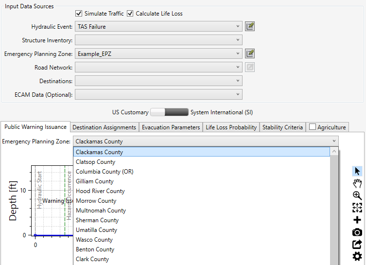
Figure: Create New Alternative Dialog Box - Public Warning Issuance Tab - EPZ Zones Available in Dropdown - The public warning issuance scenario has three parameters. Each parameter can be defined with uncertainty and is used to define when warnings are issued to the population by zone in the emergency planning zone (EPZ) (Figure).
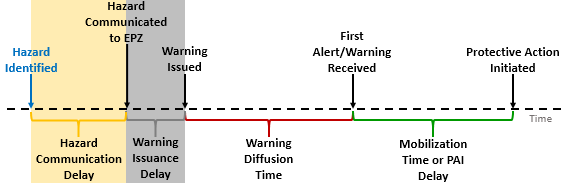
Figure: Conceptual diagram illustrating the flood warning and evacuation timeline. Highlighted sections relavant to warning issuance time are: Hazard Identified Relative Time (blue); Hazard Communication Delay (yellow); and, Warning Issuance Delay (gray) - The Imminent Hazard ID Time (Hours) parameter (Figure) is the period of time, in hours, between when the hazard is identified (ID) and the hazard occurs as defined by the selected hydraulic data. See First Hydraulic Timestep and Hazard Occurrence for more information on the hazard occurrence time. From the Uncertainty Type dropdown menu (Figure), select and define the uncertainty in imminent hazard ID time. The default is None. However, the user can choose Triangular (minimum, most likely, maximum), Normal (most likely, standard deviation), and Uniform (minimum, maximum).
- The Hazard Communication Delay (Hours) parameter (Figure) is the period of time between when the hazard is identified to when the EPZ representatives or Emergency Management Agency (EMA) is alerted. From the Uncertainty Type dropdown menu (Figure), select and define the uncertainty. The default is None. However, the user can choose Triangular (minimum, most likely, maximum), Normal (most likely, standard deviation), and Uniform (minimum, maximum).
- The Warning Issuance Delay parameter (Figure) is the time it takes from when the emergency managers receive the notification of the imminent hazard to when they issue an evacuation order to the public.
- The Warning Issuance Delay is part of the warning issuance process, but it is defined in the emergency planning zone (EPZ) dataset. However, if the warning issuance delay parameters require editing, click to open the Emergency Planning Zone Editor and edit the warning issuance delay (see EPZ Editor for further information).
NOTE: By default, the Emergency Planning Zone Editor opens to the Warning Issuance Delay tab for the first EPZ zone in the Emergency Planning Zone list. In other words, the EPZ zone selected from the Create New Alternative (e.g., Geyserville in Figure) does not modify the EPZ selected in the opened Emergency Planning Zone Editor.
- Either click OK to save the alternative and close the Create New Alternative dialog box (Figure) or select the next desired tab and continue to define the new alternative.
An example of a completed Public Warning Issuance tab is shown in the following figure (Figure).
Destination Assignments
When simulating traffic (Simulate Traffic checkbox
is selected such as in Figure), the user needs to define the
destinations for the emergency planning zones; from the Create New Alternative dialog box,
click the Destination Assignments tab (Figure).
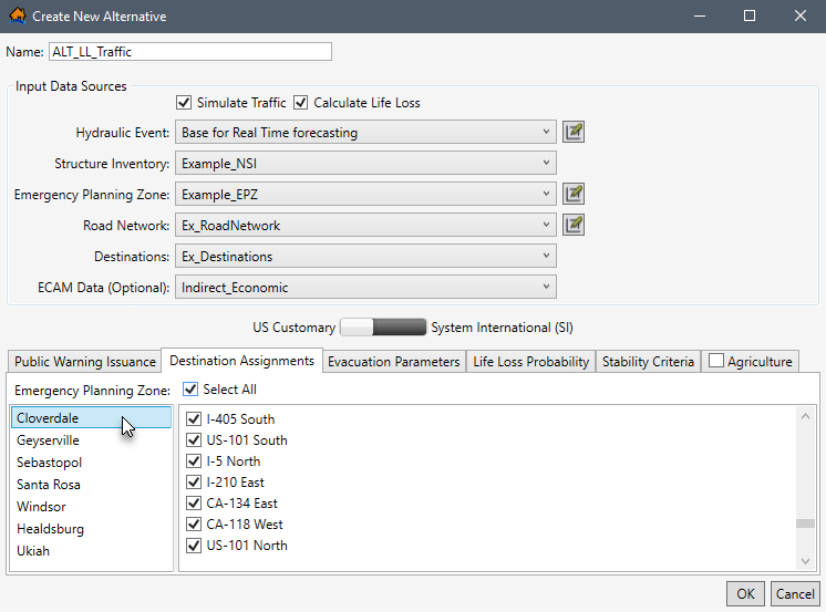
The Destination Assignments tab (Figure) is divided into two panels. The left panel lists all of the emergency planning zones in the selected EPZ dataset (e.g., Example_EPZ in Figure). Therefore, if a selected EPZ dataset has multiple zones, then the list will contain the names of the multiple zones (e.g., Cloverdate zone, Geyserville zone, and so on in Figure). The right panel provides a list of all of the destination names (e.g., I-405 South) in the destination’s dataset (e.g., Ex_Destinations in Figure).
The user can define unique (for multiple zones when present) destinations for selected EPZs. For example, if the warning message content for a particular EPZ dictates specific destination locations, those locations can be defined and people within the EPZ will attempt to evacuate to one of the specified destination locations.
To assign specific destinations to unique or multiple zones:
- From the left panel, select the desired EPZ name (e.g., Cloverdale in Figure).
- From the list of destinations in the right panel, select an individual destination or multiple destinations by checking the checkbox.
- By default, all the destinations are selected. To unselect all destinations, click Select All (Figure). Alternatively, to reselect all destinations, click Select All again.
- Continue through the list of zones and list of destinations to assign the correct destinations to the correct zones.
- Once all desired destinations have been assigned, either click OK to save the alternative and close the Create New Alternative dialog box (Figure) or select the next desired tab and continue to define the new alternative.
Evacuation Parameters
When simulating life loss, the Evacuation Parameters tab (Figure) allows the user to adjust the default traffic evacuation simulation parameters in LifeSim.
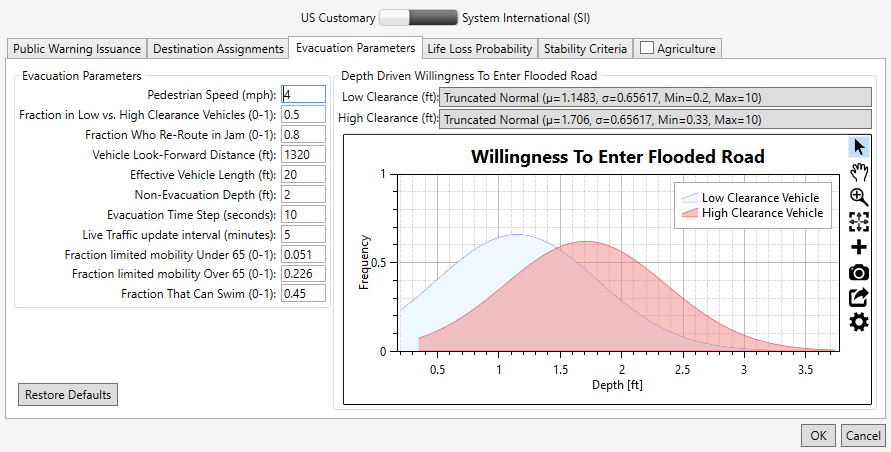
The Evacuation Parameters tab contains two panels.
Evacuation Parameters left panel: contains a list of traffic simulation parameters with defaults (Table). All available evacuation parameters are set with defaults, but the user can adjust the parameters by modifying the default values.
Depth Driven Willingness to Enter Flooded Road right panel: users can define probability density functions for low clearance (cars) and high clearance (trucks) vehicles willingness to enter (ford) flooded roads. During the evacuation simulation, vehicles encountering a flooded road will either attempt to ford the road or will attempt to turn around depending on the defined willingness to enter functions. The LifeSim Version 2.0 Technical Reference Manual, Chapter 6 provides extensive detail regarding evacuation parameters and depth driven willingness to enter flooded roads.
| Parameter | Units | Range | Default | Definition |
|---|---|---|---|---|
| Pedestrian Speed | mph | 2 to 5 | 4 | Speed of people evacuating on foot. |
| Low vs. High Clearance Vehicles | fraction | 0 to 1 | 0.5 | Fraction of people who will be evacuating in low (cars) vs. high clearance (trucks) vehicles. |
| Re-Route in Jam | fraction | 0 to 1 | 0.8 | Fraction of vehicles that will attempt to re-route when a traffic jam is reached. |
| Vehicle Look-Forward Distance | feet | N/A | 1,320 | The distance in front of a vehicle that is used to define the traffic density. |
| Effective Vehicle Length | feet | 20 to 25 | 20 | The effective length of a vehicle which determines load limits. |
| Non-Evacuation Depth | feet | 0 to 3 | 2 | Depth at a structure where people will no longer attempt to evacuate away from the structure. |
| Evacuation Time Step | seconds | 1 to 30 | 10 | The timestep of the traffic simulation engine (smaller values = more accuracy but longer simulation compute times). |
| Live Traffic Update Interval | minutes | 1 to 10 | 5 | Define how often the current traffic conditions gets updated for vehicles that re-route when reaching a traffic jam (lower values increase simulation times). |
| Limited Mobility Under 65 | fraction | 0 to 1 | 0.051 | Defines the faction of population under 65 years old that has limited mobility. |
| Limited Mobility Over 65 | fraction | 0 to 1 | 0.22 | Defines the faction of population over 65 years old that has limited mobility. |
| Can Swim | fraction | 0 to 1 | 0.45 | Defines the fraction of population that are adept at swimming. |
To edit the default traffic evacuation simulation parameters:
- From the Evacuation Parameters left panel (Figure), edit default evacuation parameters by selecting the desired cell and entering in the desired value. For example, double-click the Non-Evacuation Depth (ft) cell to highlight the default value and type in a depth in feet appropriate for the study.
- From the Depth Driven Willingness To Enter Flooded Road right panel, select the desired clearance (e.g., High Clearance in Figure) button to open the distribution selection window.
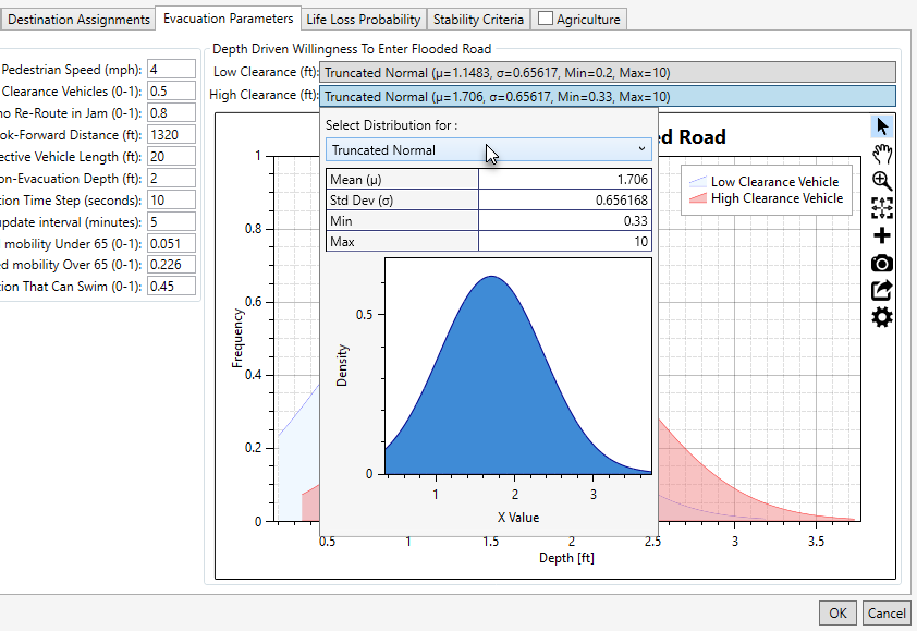
Figure: Create New Alternative Dialog Box – Evacuation Parameters Tab - Depth Driven Willingness to Enter Flooded Road Panel - Distribution Selection Window - From the distribution selection window (Figure), from the Select Distribution for dropdown list, select the desired function (e.g., Truncated Normal in Figure).
- The selected distribution updates the distribution selection window (Figure). Enter the parameters for the selected distribution in the table provided. Close the distribution selection window by clicking anywhere in the Create New Alternative dialog box (Figure). The Willingness To Enter Flooded Road plot updates dynamically (on-the-fly) with the entered probability density function. Review Table Tools for instructions on using the general plotting tools (located on the right side of the plot window) and for customizing plots.
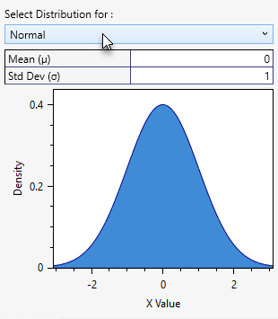
Figure: Create New Alternative Dialog Box – Evacuation Parameters Tab - Depth Driven Willingness to Enter Flooded Road Panel - Distribution Selection Window - Normal - To restore an edited parameter back to the default values, click Restore Defaults (Figure).
NOTE: the Restore Defaults button returns both the evacuation parameters and the willingness to enter flooded roads functions back to defaults. - Either click OK to save the alternative and close the Create New Alternative dialog box (Figure) or select the next desired tab and continue to define the new alternative.
Life Loss Probability
The Life Loss Probability tab (Figure) allows the user to adjust the default fatality rate curves that are used to define probability of life loss for the high and low hazard zones. In LifeSim Version 1.0, default fatality rate curves were developed for three zones: chance, compromised, and safe. However, in LifeSim Version 2.0, the original three zones were replaced with two new zones: low and high hazard. The LifeSim Version 2.0 Technical Reference Manual, Chapter 9, Section 9.2 provides a detailed explanation regarding the development of the two new zones and the fatality rate functions for the new zones.
LifeSim Version 2.0 characterizes each agent as either being in high hazard or low hazard conditions as described in Table.
| Zone | Description |
|---|---|
| High Hazard Zone | Refers to those conditions where the stability criteria or submergence criteria of the person, the vehicle (if caught while evacuating), or the structure (if not mobilized) has been exceeded. When the stability (or submergence) criteria has been exceeded, survival depends largely on chance. |
| Low Hazard Zone | Refers to those conditions where the person or group of people are exposed to relatively calm floodwaters, where the stability of the individual, group, or shelter is not at risk. A hazard exists due to the potential for bad things to happen when people come in contact with water in locations not meant for such an interaction. |
To modify the default fatality rate curves:
- From the Create New Alternative dialog box (Figure), select the Life Loss Probability tab. The Life Loss Probability tab provides a dropdown menu to select the desired Zone and view or modify the curve data (e.g., High Hazard in Figure).
The Relative Frequency of Exceedance (X-Axis) represents the probability of a receiving a particular fatality rate. The Proportional Life Loss (Y-Axis) represents the fatality rate. Using the default high hazard data (Figure), if 100 people were in the high hazard zone, 47 of them would have a 100 percent fatality rate.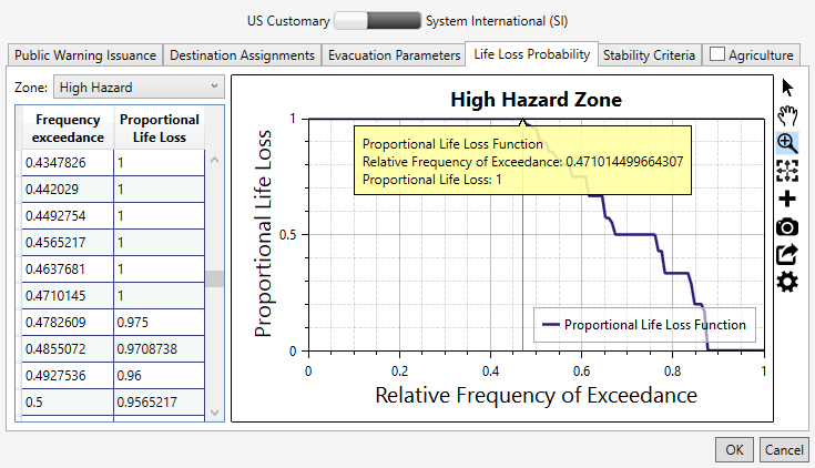
Figure: Create New Alternative Dialog Box - Life Loss Probability Tab - High Hazard Zone Selected - The default life loss probability functions can be edited manually or copied from another application (e.g., Microsoft Excel®) and pasted into the table (i.e., entire table, individual cells, columns, rows). From the table, right-click a cell (or group of selected cells) to open the shortcut menu (similar to Figure). From the shortcut menu, the user can Add, Insert, and Delete Row(s); Select All; Copy or Copy with Headers; and Paste.
Errors in the life loss probability function are highlighted in red in the table and a tooltip displays a message describing the error (as in Figure). Right-click on a header row to open the shortcut menu (Figure) to sort the table in ascending or descending order, or clear the table sorting. - The Hazard Zone plot (Figure) provides a live update for the data entered in the table. Review Table Tools for instructions on using the general plotting tools (located on the right side of the plot window) and for customizing plots.
- When done evaluating/modifying the life loss probability for the two zones, either click OK to save the alternative and close the Create New Alternative dialog box (Figure) or select the next desired tab and continue to define the new alternative.
Stability Criteria
The Create New Alternative dialog box (Figure) Stability Criteria tab (Figure) allows users to adjust the default stability criteria for three groups: human stability, and low and high clearance vehicles. The user can adjust the default stability criteria thresholds (depth, velocity, and functional) for the three groups. The LifeSim Version 2.0 Technical Reference Manual provides more information on the human and vehicle stability criteria.
To modify the default functions:
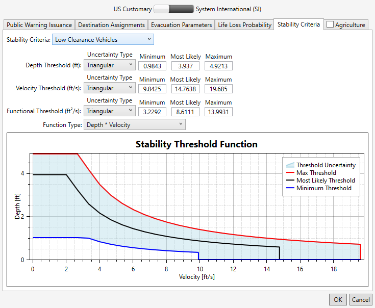
- From the Create New Alternative dialog box (Figure) Stability Criteria tab (Figure), from the Stability Criteria dropdown list, select the desired group (e.g., Low Clearance Vehicles in Figure).
- The user can modify the uncertainty about the three thresholds for the selected stability criteria group. From the Uncertainty Type dropdown menus, select the desired uncertainty type (e.g., Triangular in Figure) and define the uncertainty parameters for each threshold. Modify the listed stability criteria parameters by entering values into the fields manually.
- The Functional Threshold has an additional parameter for selecting the function type from the Function Type list (Figure), as either Depth*Velocity or Depth*(Velocity Squared).
- When done evaluating/modifying the stability criteria parameters for all three groups (humans, low and high clearance vehicles), either click OK to save the alternative and close the Create New Alternative dialog box (Figure) or select the next desired tab and continue to define the new alternative.
Agriculture
The Create New Alternative dialog box (Figure) Agriculture tab (Figure) allows users set the agriculture inventory for the alternative and enter a specific hydraulic event starting date for calculating the agricultural flood damages.
To calculate agriculture damages for the created alternative:
- From the Create New Alternative dialog box (Figure), select the Agriculture tab (Figure).
- Turn on the agricultural damages calculation option by checking the checkbox in the header of the Agriculture tab (Figure). By default, calculating agriculture damages is turned off. i.e., the checkbox is unchecked .
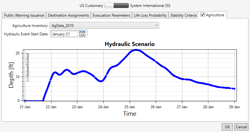
- From the Agriculture Inventory list (Figure), select the desired dataset (e.g., AgData_2010 in Figure).
- From the Hydraulic Event Start Date box (Figure), click the
 button to open the date selector window and set the desired hydraulic event starting date (e.g., January 21 in Figure).
The Hydraulic Scenario plot (Figure) updates by starting the first timestep in the selected hydraulic dataset (e.g., Base for Real Time forecasting in Figure) based on the selected Hydraulic Event Start Date. - Click OK to save the alternative and close the Create New Alternative dialog box (Figure), or select the next desired tab and continue to define and/or edit the alternative.
Edit an Alternative
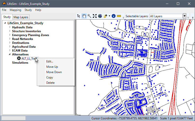
To edit an alternative, from the LifeSim main window, from the Study tab, from the Study Tree, from the Alternatives folder, right-click on an alternative name (e.g., ALT_LL_Traffic in Figure). From the shortcut menu, click Edit.
Alternatively, from the LifeSim main window, from the Study menu, point to Alternatives (Figure), point to Edit, and click on an alternative name. Either way, the Alternative Editor will open (similar to Figure). See Create an Alternative for more information regarding the editable fields in the Alternative Editor.
Copy an Alternative
To copy an alternative, from the LifeSim main window, from the Study tab, from the Study Tree, from the Alternatives folder, right-click on an alternative name (e.g., ALT_LL_Traffic in Figure). From the shortcut menu, click Copy.
Another way is from the LifeSim main window, from the Study menu, point to Alternatives (Figure), point to Copy, and click on an alternative name.
Either way, the Name of New Study Item dialog box (Figure) opens. Enter a new name in the Name box. Click OK, the Name of New Study Item dialog box closes, and the copied alternative is added to the Study Tree under the Alternatives folder.
Delete an Alternative
To delete an alternative, from the LifeSim main window, from the Study tab, from the Study Tree, from the Alternatives folder, right-click on an alternative name (e.g., ALT_LL_Traffic in Figure). From the shortcut menu, click Delete.
Another way is from the LifeSim main window, from the Study menu, point to Alternatives (Figure), point to Delete, and click on an alternative name.
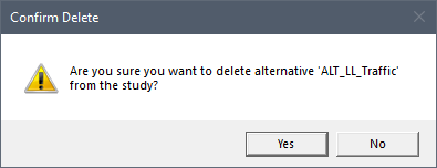
Either way, a Confirm Delete window (Figure) opens asking for confirmation to delete the selected alternative. Click Yes to confirm the deletion. The Confirm Delete window closes, and the selected alternative is deleted and no longer displays in the Study Tree under the Alternatives folder.