

Hydraulic Data
Chapter Overview
Hydraulic data are critical components of computing damages and life loss in LifeSim. Hydraulic data sources in LifeSim are generally model output from hydraulic modeling systems, such as HEC-RAS (Hydrologic Engineering Center’s River Analysis System software v.5.0 or later) [?] or FLO-2D (FLO-2D Software, Inc., 2022) [?]. For detailed life loss assessments, an unsteady hydraulic modeling approach (one-dimensional or two-dimensional, as appropriate) is used to develop the inundation boundaries, arrival times, depths, and velocities necessary to estimate potential loss of life. LifeSim interpolates the depths and velocities at roads and structures between hydraulic time steps. A shorter hydraulic time step will generally provide more hydraulically accurate computations, but also require more memory and take longer to simulate. If direct economic damage estimates are the only required output, a single maximum depth grid is the only hydraulic input requirement.
In addition to providing the spatially distributed (gridded) time series of depth and velocity, a hydrograph representing the hydraulic event must be provided. The hydrograph is a visual aid used to help develop the warning and protective action timeline. It is not used in the computations.
To support a detailed risk assessment, several flood scenarios are typically modeled and simulated. This range of scenarios could include breaches at different reservoir pool elevations or river levees as well as non-failure scenarios where flooding could lead to potential life loss. Other important considerations in hydraulic modeling include breach parameters and coincident hydrologic conditions (e.g., reservoir inflow, tributary flows and stages, status of interior drainage system). Often these additional considerations are handled through sensitivity and uncertainty analyses, and a range of potential life loss results are provided for each scenario rather than a single value (Needham, Fields, and Lehman, 2016) [?].
This chapter covers the various hydraulic input options LifeSim can use for simulations. LifeSim will use the combination of floodplain depths and velocities to calculate damages to structures, damages to agricultural assets, indirect economic impacts, and life loss consequences.
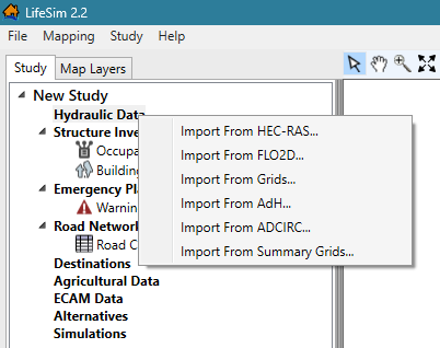
Import from HEC-RAS
LifeSim can read hydraulic data directly from HEC-RAS output produced with HEC-RAS Version 5.0 or later. To directly read the HEC-RAS output, LifeSim implements the .NET library RASMapper, developed by HEC to sample hydraulic information. RASMapper has robust sampling methods (e.g., sloping water surfaces for 2D hydraulics) to estimate depth and velocity at any location for any time step. The hydraulic time step in HEC-RAS is defined by the Mapping Output Interval.
LifeSim will automatically name the hydraulic file based on the plan name from the HEC-RAS output file. Once the data is imported into LifeSim, the file name can be edited if desired.
Import from FLO-2D
LifeSim can import hydraulic results directly from FLO-2D result files and convert them into a time series of depth and velocity compressed GeoTiff files. During the conversion process, LifeSim also creates summary grids of maximum depth, velocity, depth times velocity, and depth times velocity squared for each grid cell. The GeoTiff files are stored in the hydraulics directory of the LifeSim study. The ability to link directly with the hydraulic results reduces data processing time as converting hydraulic information to a software specific format is not needed.
Import from Grids
When hydraulic model results cannot be directly imported, model results must be converted into a time series of depth and velocity grids for use in LifeSim. If the grids are spaced at regular time intervals, the import process is greatly simplified. Otherwise, for irregular time intervals the user must input each time step and associate it to an individual depth and velocity grid cell. Other hydraulic characteristics are calculated from the depth and velocity grids as needed.
Hydraulic grid datasets can be imported into LifeSim in many gridded formats including tagged image file (*.tif), ArcInfo GRID (*.asc), and ArcGrid (*.flt).
Import from Summary Grids
The summary grids import method bypasses the need for LifeSim to calculate (pre-process) hydraulic characteristics. Instead, the necessary raster files are imported directly. Post-processing tools for several different hydraulic modeling programs, such as TUFLOW and MIKE-21, can be used to generate summary grids. Allowable file types include *.tif, *.flt, ESRI Grid, and *.vrt. The six hydraulic characteristics that can be represented by summary grids are maximum depth, maximum velocity, maximum instantaneous depth-times-velocity, arrival time for life loss calculations, arrival time for agriculture calculations, and flood duration for agriculture calculations (see Table).
| Hydraulic Summary Grid | Structural Damages | Life Loss | Agricultural Damages |
|---|---|---|---|
| Maximum Depth | Required | Required | N/A |
| Maximum Velocity | Optional | Required | N/A |
| Maximum Depth*Velocity (D*V) | Optional | Required | N/A |
| Non-Evacuation Depth Arrival Time | N/A | Required | N/A |
| Agricultural Arrival Time | N/A | N/A | Required |
| Agricultural Duration | N/A | N/A | Required |
A maximum depth grid represents the maximum depth that occurs in each grid cell over the course of a hydraulic simulation. Like maximum depth, maximum velocity and D*V (DV) represent the greatest velocity and instantaneous DV that occurred in each grid cell. DV is an important variable for stability criteria. More detailed discussion can be found in Building Stability Criteria. Because the maximum depth, maximum velocity, and maximum DV grids are not time dependent, LifeSim cannot simulate evacuation on roads when utilizing this style of hydraulic data.
An arrival time grid represents the point in time that flood water of a given depth reaches each cell. When modeling the evacuation process for life loss, LifeSim assumes that after a given flood depth is reached, individuals remaining in a structure will no longer be able to evacuate on roads, thus they will remain in the structure and vertically evacuate. For agricultural damage calculations, the arrival time grid is used to determine when water arrives at crop locations.
Duration grids contain information about the duration of time that a cell is inundated. Duration grids are used only for agricultural computations to determine damage to crops and replanting potential.
Defining Hazard Occurrence and First Time Step
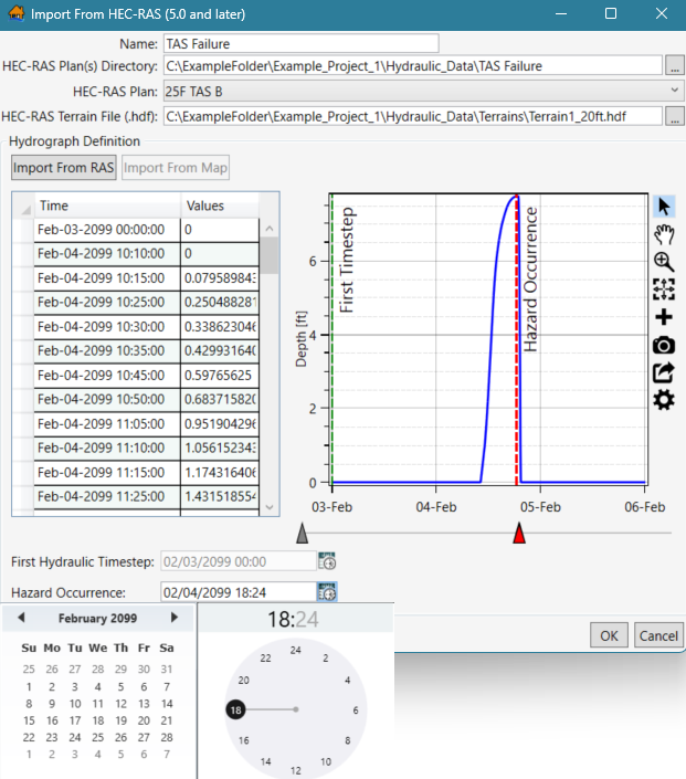
For analysis scenarios where a hydraulic time series is used, the first hydraulic time step marks the beginning of the hydraulic input. It has no bearing on other simulations within LifeSim. For example, warnings and evacuations could begin prior to the first hydraulic time step, or well after. The first hydraulic time step marks the first instance in which the hydraulic input interacts with the other model inputs (and subsequently leads to consequences). Users must define the first hydraulic time step when using the Import from FLO-2D, Import from Grids, or Import from Summary Grids options (see Figure). If using the Import from HEC-RAS option, the first hydraulic time step will automatically populate.
The hazard occurrence time must be set by the user and is defined as the instance when the hazard occurs (i.e., dam failure). In the case of a structural breach or failure scenario, the hazard occurrence should be defined as the moment of failure (see Figure). In some cases, such as internal erosion failure, there is no instantaneous moment of failure. The user must exercise discretion when assigning hazard occurrence times to such scenarios. Typically, no matter how gradual the failure, there is a point in time where the discharge increases dramatically at the point of failure, or at least more than any other time step. With internal erosion, that point is usually when the roof of the pipe collapses into a full breach.
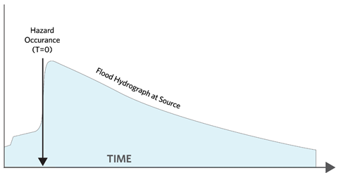
Hydrographs downstream of the failure location can be helpful to determine the hazard occurrence time in cases of instantaneous failure, such as a gate failure or total embankment collapse where a sharp increase in flow is observed. More information on the hazard occurrence time and its role in the warning and evacuation timeline is discussed in Hazard Occurrence Time.
In the hydraulic data import study component, once the hydrograph data are imported the user defines the hazard occurrence time (Figure).
Generating Hydraulic Summary Information
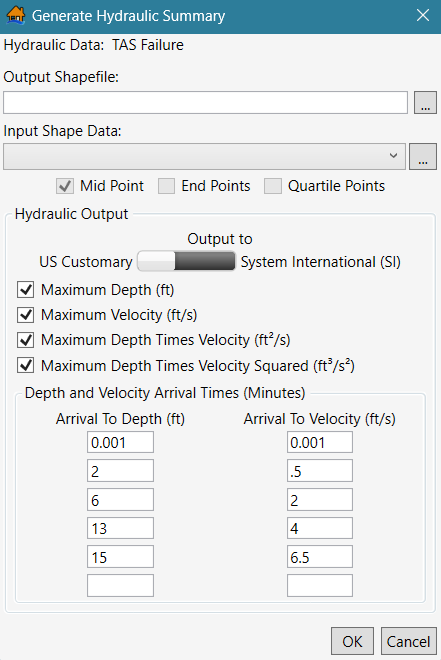
Once hydraulic information is imported into LifeSim, the user can generate a hydraulic summary for any point or line GIS shape feature. This creates an output shapefile that contains the defined summary hydraulic data at each feature in the input shape data. The user can specify which hydraulic outputs to include in the output summary, such as maximum depth, maximum velocity, maximum depth times velocity, maximum depth times velocity squared, and arrival time of depth and velocity at user specified intervals as shown in Figure.
The hydraulic summary data can be useful in identifying potential issues in the structure inventory or road network, such as structures that are inundated too quickly due to bad placement or bridges that have water under them prior to the flood event.
General Modeling Guidelines
Considerations for Hydraulic Modeling for Consequence Assessment
The user should consider the following when populating the LifeSim model with hydraulic data:
- LifeSim interpolates depth and velocity between hydraulic time steps; shorter hydraulic time steps will provide more accurate results. Generally, hydraulic model output should be no greater than a 15-minute time interval.
- Anything in the hydraulic model that impacts flood depth, velocity, or arrival time can impact LifeSim results.
- One-dimensional (1D) storage areas do not capture velocities of water or flow paths for accurate arrival time information. Instead, they assume a level pool condition filling from the lowest point in the storage area. If a 1D storage area does not capture the nature of flooding for the study area, consider a 2D representation to better reflect flooding of roads and structures.
- The hydraulic modeling hydrograph output interval and mapping output interval should be sufficient to capture steep hydraulic grade lines (and the peak) without compromising quality.
- Grid size and location should be compatible with the placement of roads, structures, and agricultural land. If grid cells are too large, they could extend beyond channel limits and damage items they should not.
Considerations for Multiple Hazard Events
When assigning the hazard occurrence time during a failure in normal weather conditions, the point is straightforward. However, if a flood is occurring – leading to failure – there may be confusion of when the "hazard" occurs. Discretion and flexibility are given to the user. However, the main consideration is that the time selected and warning times should be internally consistent. Often with large flood events, an evacuation is called based on expected flows out of channel or overtopping downstream levees. A failure of the facility under study adds a larger flood wave on top of the expected one. Historically, this second failure flood wave triggers a second round of evacuation notices to a larger area (a.k.a. double warning). Users may set the hazard occurrence at the first sign of flooding and manipulate warning and evacuation curves to represent the two warnings, or more commonly, use the failure time as the hazard occurrence and create EPZs that separate the first high-flow warning zone from the second failure warning zone with different warning times for each.
Discussion of Sensitivity to Depth, Velocity, and Arrival Time (Breach Parameters)
LifeSim samples the uncertainty of many parameters but does not currently include uncertainty in the hydraulic input. Hydraulic input data are assumed to be known with certainty. However, with all hydraulic modeling, uncertainties exist and should be considered. Often, the factors that affect model results most significantly are the failure scenario and breach parameters when simulating dam and levee failures. These parameters are highly uncertain and can affect model results miles downstream (although typically lessening with distance from the hazard source). If breach parameters impact flood depth, velocity, arrival time, or warning time, they will likely impact LifeSim results significantly. Breach parameter sensitivity testing is recommended to understand these impacts.
To test the sensitivity of breach parameters on LifeSim results, the user would:
- Run HEC-RAS using a set of breach parameters.
- Use HEC-RAS results as input to LifeSim. Run LifeSim.
- Re-run HEC-RAS using a different set of breach parameters.
- Re-run LifeSim using HEC-RAS results from Step 3.
- Compare LifeSim results from Steps 2 and 4.