
Blanket Theory Case 8
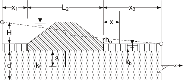
Case 8 has a semi-pervious top stratum on both the riverside and landside of the levee, and a partially penetrating seepage barrier (for example, sheet pile wall or slurry wall) into the pervious substratum is at the centerline of the levee. The pervious substratum is divided into four zones to apply the method of fragments as shown in Figure due to the partially penetrating seepage barrier. Since the top strata are semi-pervious, the effective seepage entry distance from the riverside levee toe must be calculated based on the type of seepage entrance (riverside boundary condition), and the effective seepage exit distance from the landside levee toe must be calculated based on the type of seepage exit (landside boundary condition).
Method of Analysis
The method of analysis is the same as in Case 1.
Levee Geometry
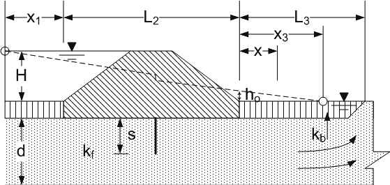
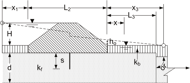
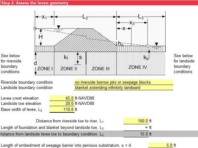
This levee geometry is the same as in Case 7, but there is a partially penetrating seepage barrier into the pervious substratum is at the centerline of the levee. Figure illustrates a blanket extending infinitely landward (Case 8a). Figure illustrates an open seepage exit (Case 8b). Figure illustrates a seepage block (impervious boundary) beyond the landside levee toe that prevents any seepage exit into the pervious foundation landside of the seepage block (Case 8c).
There is an additional input for the length of the embedment of the seepage barrier into the pervious substratum (s). Values greater than or equal to the thickness of the pervious stratum (d) have an orange background. The input is illustrated in Figure .
Pervious Substratum Characterization
The pervious stratum characterization is the same as in Case 1.
Riverside Blanket (Top Stratum) Characterization
The riverside blanket (top stratum) characterization is the same as in Case 5.
Landside Blanket (Top Stratum) Characterization
The landside blanket (top stratum) characterization is the same as in Case 6.
Blanket Theory Assumptions
The check of BT assumptions is the same as in Case 7.
Seepage Characterization
Step 7 calculates the net hydraulic head on the levee (H) the same as in Case 1. The flow or seepage per unit length of the levee (Qs) is calculated using Equation.
where:
kh,f = horizontal permeability of pervious substratum
H = net hydraulic head on the levee
d = thickness of the pervious substratum
x1 = effective seepage entrance from the riverside levee toe
x3 = effective seepage exit from the landside levee toe
K / K′ = ratio of the complete elliptic integral of the first kind to the complementary integral
The value of K / K′ is obtained from a table of complete elliptical integrals of the first kind. In Table, the modulus (m) is calculated using Equation.
where:
s = length of embedment of the seepage barrier into the pervious substratum
b = half base width of the levee = L2 / 2
| K / K′ | K / K′ | K / K′ | K / K′ | K / K′ | |||||
|---|---|---|---|---|---|---|---|---|---|
| 0.000 | 0.000 | 0.17 | 0.706 | 0.43 | 0.938 | 0.69 | 1.198 | 0.95 | 1.828 |
| 0.001 | 0.325 | 0.18 | 0.716 | 0.44 | 0.946 | 0.70 | 1.211 | 0.96 | 1.901 |
| 0.002 | 0.349 | 0.19 | 0.726 | 0.45 | 0.955 | 0.71 | 1.224 | 0.97 | 1.992 |
| 0.003 | 0.366 | 0.20 | 0.735 | 0.46 | 0.964 | 0.72 | 1.237 | 0.98 | 2.123 |
| 0.004 | 0.379 | 0.21 | 0.745 | 0.47 | 0.973 | 0.73 | 1.251 | 0.990 | 2.347 |
| 0.005 | 0.389 | 0.22 | 0.754 | 0.48 | 0.982 | 0.74 | 1.265 | 0.991 | 2.381 |
| 0.006 | 0.398 | 0.23 | 0.763 | 0.49 | 0.991 | 0.75 | 1.279 | 0.992 | 2.418 |
| 0.007 | 0.406 | 0.24 | 0.773 | 0.50 | 1.000 | 0.76 | 1.294 | 0.993 | 2.461 |
| 0.008 | 0.413 | 0.25 | 0.782 | 0.51 | 1.009 | 0.77 | 1.310 | 0.994 | 2.510 |
| 0.009 | 0.420 | 0.26 | 0.791 | 0.52 | 1.018 | 0.78 | 1.326 | 0.995 | 2.568 |
| 0.01 | 0.426 | 0.27 | 0.800 | 0.53 | 1.028 | 0.79 | 1.343 | 0.996 | 2.639 |
| 0.02 | 0.471 | 0.28 | 0.808 | 0.54 | 1.037 | 0.80 | 1.360 | 0.997 | 2.731 |
| 0.03 | 0.502 | 0.29 | 0.817 | 0.55 | 1.047 | 0.81 | 1.377 | 0.998 | 2.860 |
| 0.04 | 0.526 | 0.30 | 0.826 | 0.56 | 1.057 | 0.82 | 1.397 | 0.999 | 3.081 |
| 0.05 | 0.547 | 0.31 | 0.834 | 0.57 | 1.066 | 0.83 | 1.416 | 0.9991 | 3.115 |
| 0.06 | 0.565 | 0.32 | 0.843 | 0.58 | 1.076 | 0.84 | 1.439 | 0.9992 | 3.152 |
| 0.07 | 0.582 | 0.33 | 0.852 | 0.59 | 1.087 | 0.85 | 1.462 | 0.9993 | 3.195 |
| 0.08 | 0.598 | 0.34 | 0.860 | 0.60 | 1.098 | 0.86 | 1.484 | 0.9994 | 3.244 |
| 0.09 | 0.612 | 0.35 | 0.869 | 0.61 | 1.107 | 0.87 | 1.511 | 0.9995 | 3.302 |
| 0.10 | 0.625 | 0.36 | 0.877 | 0.62 | 1.118 | 0.88 | 1.538 | 0.9996 | 3.373 |
| 0.11 | 0.638 | 0.37 | 0.886 | 0.63 | 1.129 | 0.89 | 1.567 | 0.9997 | 3.465 |
| 0.12 | 0.650 | 0.38 | 0.895 | 0.64 | 1.140 | 0.90 | 1.600 | 0.9998 | 3.594 |
| 0.13 | 0.662 | 0.39 | 0.903 | 0.65 | 1.151 | 0.91 | 1.634 | 0.9999 | 3.814 |
| 0.14 | 0.674 | 0.40 | 0.911 | 0.66 | 1.162 | 0.92 | 1.672 | 1 | ∞ |
| 0.15 | 0.684 | 0.41 | 0.920 | 0.67 | 1.174 | 0.93 | 1.718 | ||
| 0.16 | 0.695 | 0.42 | 0.929 | 0.68 | 1.186 | 0.94 | 1.770 | ||
To interpolate intermediate values of K / K′ for m2 between 0.9999 and 1 in Table, the maximum number that can be stored by Excel of 1.79769313486232E308 is used for K / K′ = ∞. If the seepage barrier is fully penetrating (s ≥ d), m is 1; K / K′ = ∞; and Qs = 0.
The format for the tabular output is the same as in Case 1.
Likelihood of Heave/Blowout at Landside Toe
Step 8 calculates the excess hydraulic head at the landside levee toe (ho) using Equation.
where:
H = net hydraulic head on the levee
d = thickness of the pervious substratum
x1 = effective seepage entrance from the riverside levee toe
x3 = effective seepage exit from the landside levee toe
The vertical seepage exit gradient at the landside levee toe (ix) is calculated the same as in Case 6, and the factor of safety against heave/blowout (based on vertical seepage gradients) at the landside levee toe (FSvg) is calculated the same as in Case 2. The format for the tabular and graphical output is the same as in Case 2.
Likelihood of Heave/Blowout at Given Distance from Landside Toe
If the blanket extends infinitely landward, Step 9 calculates the excess hydraulic head at a distance x from the landside levee toe (hx) using Equation.
where:
ho = excess hydraulic head at the landside levee toe
x = distance from the landside levee toe
If a seepage block exists landward of the landside levee toe that prevents any seepage exit into the pervious foundation landside of the seepage block, Step 9 calculates the excess hydraulic head at a distance x from the landside levee toe (hx) using Equation 40.
where:
ho = excess hydraulic head at the landside levee toe
cbl = constant for the landside blanket
L3 = distance from the landside levee toe to the seepage block for the “seepage block (impervious boundary)” boundary condition
x = distance from the landside levee toe
If an open seepage exit exists landward of the landside levee toe, Step 9 calculates the excess hydraulic head at a distance x from the landside levee toe (hx) using Equation.
where:
ho = excess hydraulic head at the landside levee toe
cbl = constant for the landside blanket
L3 = distance from the landside levee toe to the open seepage exit for the “open seepage exit” boundary condition
x = distance from the landside levee toe
The vertical seepage exit gradient at a distance x from the landside levee toe (iv,x) is calculated the same as in Case 6, and the factor of safety against heave/blowout (based on vertical seepage gradients) at a distance x from the landside levee toe (FSvg,x) is calculated the same as in Case 2. The format for the tabular and graphical output is the same as in Case 2.