
Blanket Theory Case 6
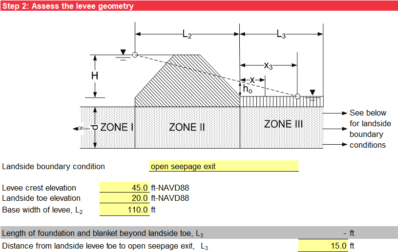
Case 6 has a semi-pervious top stratum on only the landside of the levee. The pervious substratum is divided into three zones to apply the method of fragments as shown in Figure. The difference between Cases 4 and 6 is that there is an impervious top stratum on the landside for Case 4 while the top stratum is semi-pervious for Case 6. Therefore, the effective seepage exit distance from the landside levee toe must be calculated based on the type of seepage exit (landside boundary condition).
Method of Analysis
The method of analysis is the same as in Case 1.
Levee Geometry
Step 2 characterizes the levee geometry. The input includes the levee crest elevation, landside levee toe elevation, and base width of levee (L2). Use the drop-down list to select the landside boundary condition. The options for the type of seepage exit include:
-
A blanket extending infinitely landward
-
An open seepage exit
-
A seepage block (impervious boundary) beyond the landside levee toe that prevents any seepage exit into the pervious foundation landside of the seepage block.
For “blanket extending infinitely landward,” no input is needed for L3 since it is infinitely long. For “open seepage exit,” the input for L3 is the distance from the landside levee toe to the borrow pit. For “seepage block (impervious boundary),” the input for L3 is the distance from the landside toe to the seepage block. The input is illustrated in Figure .
Pervious Substratum Characterization
The pervious stratum characterization is the same as in Case 1.
Landside Blanket (Top Stratum) Characterization
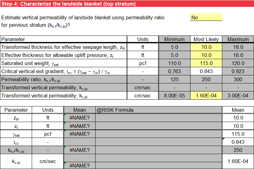
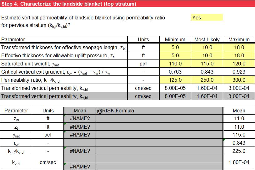
The selection in step 1 affects the input for step 4, and cells that do not apply have a gray background. These cells are not used in subsequent calculations even if data is present. The input includes the transformed thickness for effective seepage length (zbl), effective thickness for allowable uplift pressure (zt), saturated unit weight of the landside blanket (gsat), and transformed vertical permeability of the landside blanket (kv,bl).
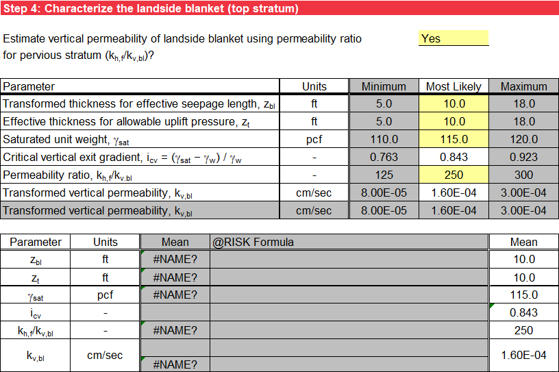
Use the drop-down list to select the method of estimating the transformed vertical permeability of the landside blanket. Input the transformed vertical permeability directly or calculate it using an input permeability ratio (kh,f / kv,bl).
For a deterministic analysis, input only the most likely values. The mean values used for subsequent calculations are the most likely (or mode) values. Figure illustrates the deterministic input. Figure illustrates the deterministic input for permeability ratio as input.
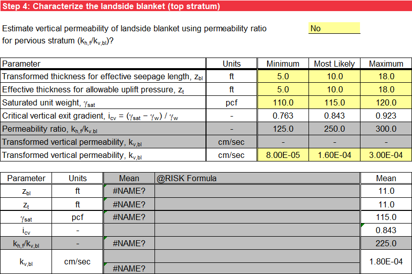
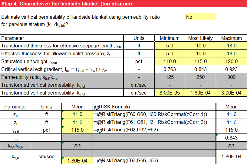
For probabilistic analysis without using @RISK, input the minimum and maximum values in addition to the most likely value, and triangular distributions represent the random variables. The mean values used in subsequent calculations are the average of the minimum, most likely, and maximum values. Figure illustrates the probabilistic input without using @RISK. Figure illustrates the probabilistic input without using @RISK for permeability ratio as input.
For probabilistic analysis using @RISK, input the minimum, most likely, and maximum values of the random variables, and use an @RISK formula for a triangular distribution in the third column as a default. Alternatively, input a valid @RISK distribution in lieu of this default formula, and the user-specified input displays in the fourth column. The mean values used in subsequent calculations are the mean for the @RISK distribution entered in the third column. Figure illustrates the probabilistic input using @RISK. Figure illustrates the probabilistic input without using @RISK for permeability ratio as input.
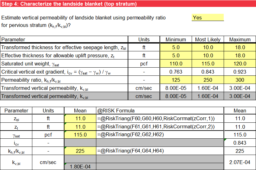
The thicknesses zbl and zt are positively correlated. For probabilistic analysis, values for the distributions for zbl and zt must be sampled in the same direction. If a high value of zbl is sampled, a high value of zt must be sampled; if a low value of zbl is sampled, a low value of zt must be sampled. For probabilistic analysis without using @RISK, this correlation is accounted for by sampling the same percentile from each distribution. For probabilistic analysis using @RISK, the correlation matrix named “zCorr” defined on the BT Transformation worksheet must be added to the end of the user-specified input distributions for zbl and zt using the @RISK RiskCorrmat property function. Use RiskCorrmat(zCorr,1) for zbl and RiskCorrmat(zCorr,2) for zt. For example, the triangular input distributions of RiskTriang(F60,G60,H60) for zbl and RiskTriang(F61,G61,H61) for zt become RiskTriang(F60,G60,H60,RiskCorrmat(zCorr,1)) and RiskTriang(F61,G61,H61,RiskCorrmat(zCorr,2)), respectively.
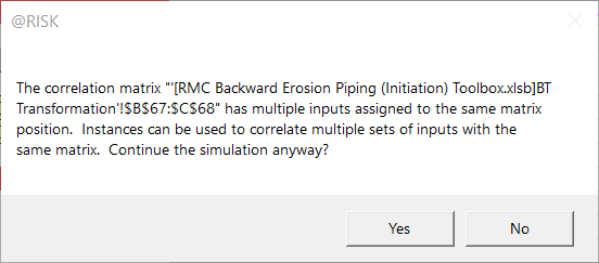
For probabilistic analysis using @RISK, if more than one of the BT Case 6, BT Case 7, and BT Case 8 worksheets exist in the active workbook, @RISK returns a warning message when the simulate button in the @RISK ribbon is selected as shown in Figure. (The workbook name in brackets matches the user’s active workbook name.) Select “Yes” to continue the simulation because the same correlation matrix (named range of “zCorr” on the BT Transformation worksheet) is used for the input distributions for zbl and zt on the BT Case 6, BT Case 7, and BT Case 8 worksheets.
If the blanket extends infinitely landward, the effective seepage exit distance from the landside levee toe (x3) is calculated using Equation and Equation.
where:
cbl = constant for the landside blanket
where:
kh,f = horizontal permeability of pervious substratum
d = thickness of the pervious substratum
kv,bl = transformed vertical permeability of the landside blanket (top substratum)
zbr = transformed thickness of the riverside blanket (top substratum)
If a seepage block exists landward of the landside levee toe that prevents any seepage exit into the pervious foundation landside of the seepage block, the effective seepage exit distance from the landside levee toe (x3) is calculated using Equation:
where:
L3 = distance from the landside levee toe to the seepage block for the “seepage block (impervious boundary)” boundary condition
If an open seepage exit exists landward of the landside levee toe, the effective seepage exit distance from the landside levee toe (x3) is calculated using Equation:
where:
L3 = distance from the landside levee toe to the open seepage exit for the “open seepage exit” boundary condition
The landside boundary condition selection in step 2 affects the equation for x3 used in step 4, and cells that do not apply have a gray background.
Blanket Theory Assumptions
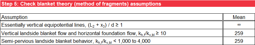
Step 5 checks the BT (method of fragments) assumptions against the input parameters to ensure essentially vertical equipotential lines, vertical flow through the blanket and horizontal flow through the pervious foundation, and semi-pervious blanket behavior. For permeability ratios greater than about 1,000 to 4,000, the semi-pervious blanket is effectively impervious, and Case 4 is more appropriate than Case 6. For deterministic analysis, the assumptions are checked for the most likely values of the random variables. For probabilistic analysis, the assumptions are checked for the mean values of the random variables. Values outside of the model assumptions have an orange background. For a blanket extending infinitely landward (L3 = ∞), (L2 + x3) / d = ∞ for all values of d. Figure illustrates the check of BT assumptions.
Seepage Characterization
Step 6 calculates the net hydraulic head on the levee (H) the same as in Case 1. The flow or seepage per unit length of the levee (Qs) is calculated using Equation.
where:
kh,f = horizontal permeability of pervious substratum
H = net hydraulic head on the levee
L2 = base width of the levee
d = thickness of the pervious substratum
x3 = effective seepage exit from the landside levee toe
The format for the tabular output is the same as in Case 1.
Likelihood of Heave/Blowout at Landside Toe
Step 7 calculates the excess hydraulic head at the landside levee toe (ho) using Equation.
where:
H = net hydraulic head on the levee
L2 = base width of the levee
d = thickness of the pervious substratum
x3 = effective seepage exit from the landside levee toe
The vertical seepage exit gradient at the landside levee toe (iv) is calculated using Equation.
where:
ho = excess hydraulic head at the landside levee toe
zt = effective thickness of the landside blanket (top stratum)
The factor of safety against heave/blowout (based on vertical seepage gradients) at the landside levee toe (FSvg) is calculated the same as in Case 2. The format for the tabular and graphical output is the same as in Case 2.
Likelihood of Heave/Blowout at Given Distance from Landside Toe
If the blanket extends infinitely landward, Step 8 calculates the excess hydraulic head at a distance x from the landside levee toe (hx) using Equation.
where:
ho = excess hydraulic head at the landside levee toe
cbl = constant for the landside blanket
x = distance from the landside levee toe
If a seepage block exists landward of the landside levee toe that prevents any seepage exit into the pervious foundation landside of the seepage block, Step 8 calculates the excess hydraulic head at a distance x from the landside levee toe (hx) using Equation.
where:
ho = excess hydraulic head at the landside levee toe
cbl = constant for the landside blanket
L3 = distance from the landside levee toe to the seepage block for the “seepage block (impervious boundary)” boundary condition
x = distance from the landside levee toe
If an open seepage exit exists landward of the landside levee toe, Step 8 calculates the excess hydraulic head at a distance x from the landside levee toe (hx) using Equation.
where:
ho = excess hydraulic head at the landside levee toe
cbl = constant for the landside blanket
L3 = distance from the landside levee toe to the open seepage exit for the “open seepage exit” boundary condition
x = distance from the landside levee toe
The vertical seepage exit gradient at a distance x from the landside levee toe (iv,x) is calculated using Equation.
where:
hx = excess hydraulic head at a distance x from the landside levee toe
zt = effective thickness of the landside blanket (top stratum)
The factor of safety against heave/blowout (based on vertical seepage gradients) at a distance x from the landside levee toe (FSvg,x) is calculated the same as in Case 2. The format for the tabular and graphical output is the same as in Case 2.