
Blanket Theory Case 7
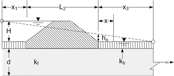
Case 7 has a semi-pervious top stratum on both the riverside and landside of the levee. The pervious substratum is divided into three zones to apply the method of fragments as shown in Figure. The difference between Cases 2 and 7 is that there is an impervious top stratum on both the riverside and landside of the levee for Case 2, while the top strata are semi-pervious for Case 7. Therefore, the effective seepage entry distance from the riverside levee toe must be calculated based on the type of seepage entrance (riverside boundary condition), and the effective seepage exit distance from the landside levee toe must be calculated based on the type of seepage exit (landside boundary condition).
Method of Analysis
The method of analysis is the same as in Case 1.
Levee Geometry
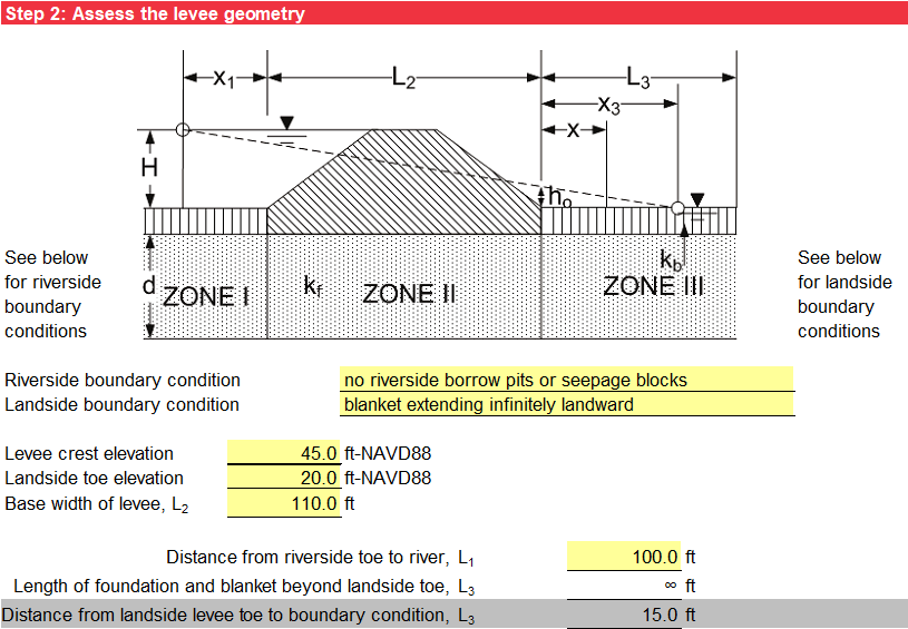
Step 2 characterizes the levee geometry. The input includes the levee crest elevation, landside levee toe elevation, and base width of levee (L2). Use the drop-down list to select the riverside boundary condition. The options for the type of seepage entrance include:
-
No riverside borrow pits or seepage blocks
-
Riverside borrow pit (open seepage entrance) that penetrates the blanket and extends to the pervious substratum
-
A seepage block (impervious boundary) between the riverside levee toe and the river that prevents any seepage entrance into the pervious foundation riverside of the seepage block
For “no riverside borrow pits or seepage blocks,” the input for L1 is the distance from the riverside levee toe to the river. For “riverside borrow pit (open seepage entrance),” the input for L1 is the distance from the riverside levee toe to the borrow pit. For “seepage block (impervious boundary),” the input for L1 is the distance from the riverside levee toe to the seepage block.
Use the drop-down list to select the landside boundary condition. The options for the type of seepage exit include:
-
A blanket extending infinitely landward as illustrated in Figure (Case 7a)
-
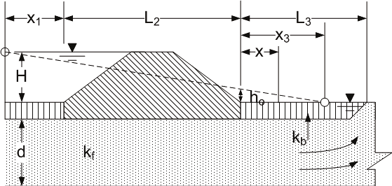
An open seepage exit as illustrated in Figure (Case 7b)
-
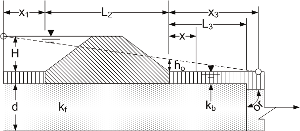
A seepage block (impervious boundary) beyond the landside levee toe that prevents any seepage exit into the pervious foundation landside of the seepage block as illustrated in Figure (Case 7c)
For “blanket extending infinitely landward,” no input is needed for L3 since it is infinitely long. For “open seepage exit,” the input for L3 is the distance from the landside levee toe to the borrow pit. For “seepage block (impervious boundary),” the input for L3 is the distance from the landside toe to the seepage block. The input is illustrated in Figure.
Pervious Substratum Characterization
The pervious stratum characterization is the same as in Case 1.
Riverside Blanket (Top Stratum) Characterization
The riverside blanket (top stratum) characterization is the same as in Case 5.
Landside Blanket (Top Stratum) Characterization
The landside blanket (top stratum) characterization is the same as in Case 6.
Blanket Theory Assumptions
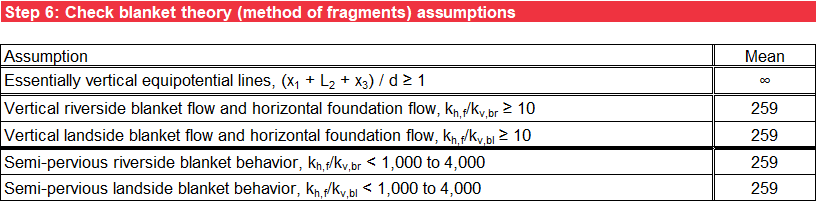
Step 6 checks the BT (method of fragments) assumptions against the input parameters to ensure essentially vertical equipotential lines, vertical flow through the blanket and horizontal flow through the pervious foundation, and semi-pervious blanket behavior. For permeability ratios greater than about 1,000 to 4,000, the semi-pervious blankets are effectively impervious, and Case 2 is more appropriate than Case 7. For deterministic analysis, the assumptions are checked for the most likely values of the random variables. For probabilistic analysis, the assumptions are checked for the mean values of the random variables. Values outside of the model assumptions have an orange background. For a blanket extending infinitely landward (L3 = ∞), (x1 + L2 + x3) / d = ∞ for all values of d. Figure illustrates the check of BT assumptions.
Seepage Characterization
Step 7 calculates the net hydraulic head on the levee (H) the same as in Case 1. The flow or seepage per unit length of the levee (Qs) is calculated using Equation.
where:
kh,f = horizontal permeability of pervious substratum
H = net hydraulic head on the levee
L2 = base width of the levee
d = thickness of the pervious substratum
x1 = effective seepage entrance from the riverside levee toe
x3 = effective seepage exit from the landside levee toe
The format for the tabular output is the same as in Case 1.
Likelihood of Heave/Blowout at Landside Toe
Step 8 calculates the excess hydraulic head at the landside levee toe (ho) using Equation.
where:
H = net hydraulic head on the levee
L2 = base width of the levee
d = thickness of the pervious substratum
x1 = effective seepage entrance from the riverside levee toe
x3 = effective seepage exit from the landside levee toe
The vertical seepage exit gradient at the landside levee toe (iv) is calculated the same as in Case 6, and the factor of safety against heave/blowout (based on vertical seepage gradients) at the landside levee toe (FSvg) is calculated the same as in Case 2. The format for the tabular and graphical output is the same as in Case 2.
Likelihood of Heave/Blowout at Given Distance from Landside Toe
The vertical seepage exit gradient at a distance x from the landside levee toe (iv,x) is calculated the same as in Case 6, and the factor of safety against heave/blowout (based on vertical seepage gradients) at a distance x from the landside levee toe (FSvg,x) is calculated the same as in Case 2. The format for the tabular and graphical output is the same as in Case 2.