
Blanket Theory Case 4
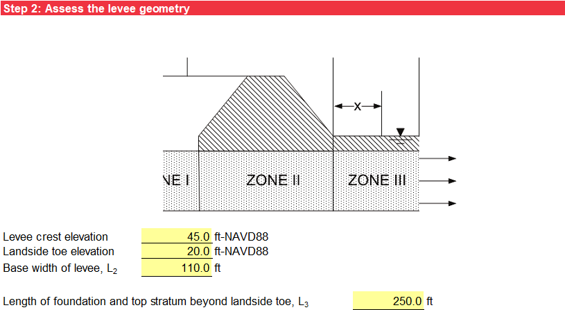
Case 4 has an impervious top stratum on only the landside of the levee. The pervious substratum is divided into three zones to apply the method of fragments as shown in Figure.
Method of Analysis
The method of analysis is the same as in Case 1.
Levee Geometry
Step 2 characterizes the levee geometry. The input includes the levee crest elevation, landside toe elevation, base width of levee (L2), and length of the foundation and top stratum beyond the landside levee toe (L3), as illustrated in Figure.
Pervious Substratum Characterization
The pervious stratum characterization is the same as in Case 1.
Landside Blanket (Top Stratum) Characterization
The landside blanket (top stratum) characterization is the same as in Case 2.
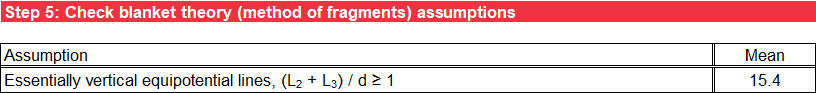
Blanket Theory Assumptions
Step 5 checks the BT (method of fragments) assumptions against the input parameters to ensure essentially vertical equipotential lines. For deterministic analysis, the assumptions are checked for the most likely values of the random variables. For probabilistic analysis, the assumptions are checked for the mean values of the random variables. Values outside of the model assumptions have an orange background. Figure illustrates the check of BT assumptions.
Seepage Characterization
Step 6 calculates the net hydraulic head on the levee (H) the same as in Case 1. The flow or seepage per unit length of the levee (Qs) is calculated using Equation.
where:
kh,f = horizontal permeability of pervious substratum
H = net hydraulic head on the levee
L2 = base width of the levee
L3 = length of the foundation and top stratum beyond the landside levee toe
d = thickness of the pervious substratum
The format for the tabular output is the same as in Case 1.
Likelihood of Heave/Blowout at Landside Toe
Step 7 calculates the excess hydraulic head at the landside levee toe (ho) using Equation.
where:
H = net hydraulic head on the levee
L2 = base width of the levee
L3 = length of the foundation and top stratum beyond the landside levee toe
d = thickness of the pervious substratum
The vertical seepage exit gradient at the landside levee toe (iv) and factor of safety against heave/blowout (based on vertical seepage gradients) at the landside levee toe (FSvg) are calculated the same as in Case 2. The format for the tabular and graphical output is the same as in Case 2.
Likelihood of Heave/Blowout at Given Distance from Landside Toe
Step 8 calculates the excess hydraulic head at a distance x from the landside levee toe (hx) using Equation.
where:
ho = excess hydraulic head at the landside levee toe
L3 = length of the foundation and top stratum beyond the landside levee toe
x = distance from the landside levee toe
The vertical seepage exit gradient at a distance x from the landside levee toe (iv,x) and factor of safety against heave/blowout (based on vertical seepage gradients) at a distance x from the landside levee toe (FSvg,x) are calculated the same as in Case 2. The format for the tabular and graphical output is the same as in Case 2.