
Iron Pipe
Ductile and cast iron pipes are most often associated with utility distribution systems for water supply, gas lines, etc. The primary difference between the two types of iron is metallurgy. Cast iron has small flakes of graphite, but ductile iron contains spherical graphite nodules that make it more durable and malleable. Ductile iron, as its name implies, is a flexible material, whereas cast iron is more brittle. Cast iron has been around for centuries, but ductile iron first saw commercial use in the mid-20th century. Due to its brittle nature, cast iron pipes typically are much thicker than ductile iron pipes of the same inside diameter.
The performance of iron pipes is generally controlled by external corrosion, since abrasive bedloads are usually not present. Metal loss rates where abrasive conditions are not a concern are a function of external corrosion. Ductile iron pipes, which largely replaced cast iron pipes in water distribution systems in the 1970s, are similar to thicker galvanized steel pipes in terms of external corrosion.
Some projects may use ductile or cast iron pipes as gravity drainage structures. If this occurs, evaluate the pipe as a steel pipe using the Steel and Aluminum Pipe worksheet, but with the modified thickness for the iron. The Iron Pipe worksheet applies only to utility distribution pipes that are pressurized with no bedload present.
Pipe Material
In Step 1, select the applicable type of iron material using the drop-down list, as illustrated in Figure. The two choices are ductile iron or cast iron.

If the iron type is unknown, the installation period may offer a clue. If installed before 1970, the pipe is likely cast iron. If installed after 1980, the pipe is likely ductile iron. The 1970s were a transition period for the industry where both types of pipes were commonly used. If the pipe was installed sometime in the 1970s, use the ductile iron pipe wall thickness for the evaluation, since it is a more conservative approach to the evaluation due to ductile iron pipe having thinner walls.
Pipe Wall Thickness
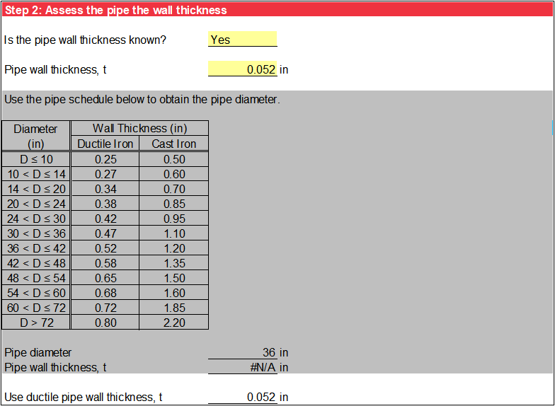
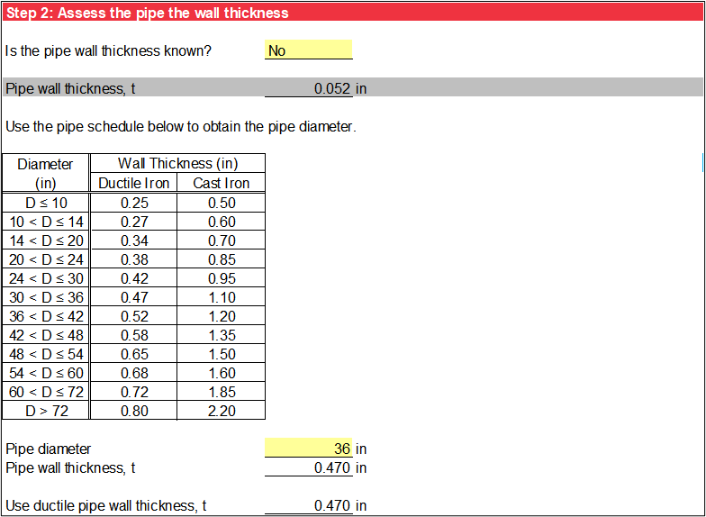
Step 2 assesses the pipe wall thickness. If the pipe wall thickness is known, select Yes using the drop-down list and specify it as shown in Figure. If the pipe wall thickness is not known, select No using the drop-down list to obtain the pipe wall thickness from the pipe schedule based on the pipe type (from step 1) and the user-specified pipe diameter, as illustrated in Figure. The wall thicknesses in Figure were adapted from Cast Iron Pipe Research Association (CIPRA) (1927) and Ductile Iron Pipe Research Association (DIPRA) (2016) for ductile iron pipe and cast iron pipe, respectively.
Corrosive Environment Characterization
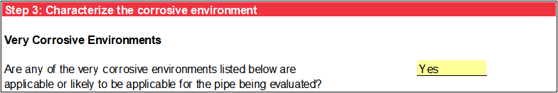
Step 3 characterizes the corrosive environment. The first part of step 3 assesses the presence of very corrosive environments due to stray electrical current, extremely acidic (pH less than 4) conditions, microbiological (anaerobic) corrosion, chloride corrosion, or damaging soils. These environments are the same as steel and aluminum pipe. If any of these very corrosive environments are applicable or likely applicable, select Yes as illustrated in Figure. Otherwise, select No.
The second part of step 3 assesses the presence of corrosive environments due to highly acidic conditions and moderately corrosive soils, which include the following:
-
Highly acidic conditions: Soil or water that is very acidic (pH between 4 and 5) is known to corrode metal rapidly. Acidic conditions are fairly widespread in areas east of the Mississippi River due to industrialization, acidic rainfall, and heavily vegetated areas. If the soil, water, or effluent around or flowing through the pipe is extremely acidic (pH < 4), assess it as very corrosive.
-
Moderately corrosive soils: Soils considered corrosive (but not very corrosive) include lean clays, loess, silts, and silty clay/clayey silt mixtures with low resistivity values (2,000 to 5,000 Ω-cm), but not as extreme as very corrosive soils (Gabriel and Moran 1998) [?], Kroon et al. (2004) [?], and Potter 1988 [?]).
If any of these corrosive environments are applicable or likely applicable, select Yes using the drop-down list as illustrated in Figure. Otherwise, select No.
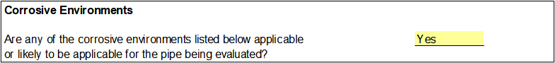
If Yes was selected from the first drop-down list, a very corrosive environment exists or is likely to exist. If No was selected from the first drop-down list (very corrosive environment does not exist or is unlikely to exist) and Yes was selected from the second drop-down list, a corrosive environment exists or is likely to exist. If No was selected from both drop-down lists, the corrosive environment is characterized as mild.
Pipe Material Loss Rate
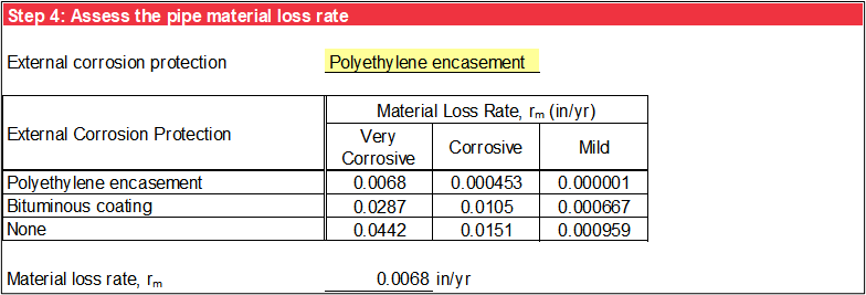
Step 4 assesses the external pipe material loss rate (rm), as illustrated in Figure. Select the corrosion protection applied to the exterior surface of the iron pipe using the drop-down list. The three options are Polyethylene encasement, Bituminous coating, or None. The material loss rate is obtained using a lookup table based on the corrosive environment (from step 3) and the user-specified external corrosion protection. The pipe material loss rates (inches per year) were developed by synthesizing several studies in a wide range of operating environments including, but not limited to, Kroon et al. (2004) [?], Bonds et al. (2005) [?], Gabriel and Moran (1998) [?], DIPRA (2017) [?], and Szeliga and Simpson (2003) [?].
Remaining Service Life
The service life of the pipe is calculated as the original pipe wall thickness (t) divided by the material loss rate (rm). Specify the number of years in service (N).
The remaining service life (T) is calculated by subtracting the number of years in service (N) from the service life (L). If the remaining service life is less than or equal to 5 years, the cell has an orange background. A negative remaining service life is the number of years exceeding the service life. The calculation is illustrated in Figure.

The remaining service life characterization is the same as steel and aluminum pipe.