
Background
Internal migration is the erosion of soil particles into open defects that initiates voids at the interface with the soil that expand (or stope) upward as temporary roofs collapse. Soil particles migrate downward primarily due to gravity and are aggravated by seepage or precipitation. For foundation defects, soil particles that drop to the bottom of the void are carried away by seepage through an unfiltered exit. For conduits, pipes, and culverts, the soil particles are carried by flow through the pipe. This usually results in sinkhole formation. This toolbox helps assess the likelihood of an open defect (flaw) in conduits, pipes, and culverts of unknown condition. The RMC Concentrated Leak Erosion (Initiation) and RMC Backward Erosion Piping (Progression) Toolboxes help assess the likelihood of internal erosion along conduits, pipes, and culverts.
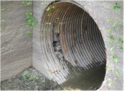
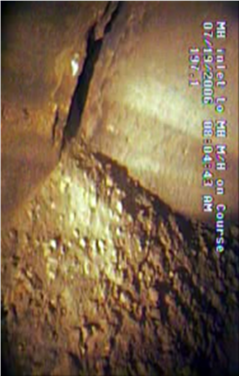
Using this toolbox is not necessary if the condition of the pipe and presence of open defects are known to exist, as shown in Figure, or from a video inspection, as shown in Figure. Even if a video inspection reveals no defects, that does not necessarily mean none exist. The invert of the pipe must be clear of debris, bedload, and water/effluent to determine the actual condition. This is extremely important because the invert of the pipe is the area most susceptible to damage due to its routine exposure to flow and bedload. If these conditions are met (full interior of pipe clearly visible for walkthrough or video inspection within 5 years of the evaluation) and no defects are found, using this toolbox is not necessary, because the presence of an open defect is considered remote.
In addition to embedded pipes whose condition is known, those that have been constructed “up and over” embankments or floodwalls (or in the overbuild section of an embankment) typically do not require analysis with the toolbox because they usually are not critical from an internal erosion standpoint. Pipes located up and over can have defects, but the embankment or supporting material around a floodwall usually cannot be transported through the defect. Pipes located in the extreme upper reaches of the embankment (in the overbuild or freeboard section) generally do not have enough hydraulic gradient to transport surrounding material through an open defect. Even if embankment material is lost through the open defect of a pipe in the overbuild or freeboard section, only a small portion of the embankment is affected due to the location of the pipe.
This toolbox estimates the remaining service life for steel, aluminum, concrete, ductile iron, cast iron, plastic, and clay pipes. The assessment of steel, aluminum, and concrete pipes is associated with degradation along the invert of the gravity flow pipes based on numerous historic testing experiments, field studies, and the actual service life of pipes from numerous individual state Department of Transportation studies. Iron (ductile and cast) pipes are typically used for utility distribution lines where bedload along the invert does not exist. Therefore, iron pipes are evaluated for external corrosion effects. Plastic pipes are being used much more frequently. They offer potential advantages when it comes to corrosion resistance, ease of installation, invert wear, etc. However, much less is known about the long-term performance of plastic pipes embedded within embankments. The toolbox uses a default service life for plastic pipes until better historic performance information becomes available. Lastly, various types of clay pipes have been used for centuries to convey water and other effluent. The performance of clay pipes is typically driven by joint separation caused by external protrusions (such as tree roots) or differential settlement. The toolbox uses a default service life for clay pipes when their condition is unknown.
Other types of pipe materials could potentially be embedded within or under an embankment or floodwall. This toolbox can provide a rough estimate of remaining service life by considering both the pipe’s purpose/use and base material. Use this information to select the most appropriate corresponding pipe material from the toolbox for evaluation. Table provides several examples for reference.
| Pipe Material | Pipe Use/Purpose | Suggested Worksheet |
|---|---|---|
| Structural steel | Gravity drainage flow | Steel and Aluminum |
| Structural steel | Other uses | Iron (modified pipe thickness) |
| Fiberglass | Any use | Plastic |
| Brick or masonry | Any use | None recommended |
| Ceramic | Any use | Clay |
| Lead | Gravity drainage flow | Steel and Aluminum |
| Lead | Other uses | Iron |
| Coal tar wood fiber | Any use | None recommended |
| Asbestos cement | Any use | Concrete |
Engineer Manual (EM) 1110-2-2902 (USACE 2020) [?] provides risk-informed guidance for the life cycle of conduits, pipes, and culverts. There are important differences between this manual and EM 1110-2-2902 with respect to a pipe’s operating environment. The toolbox was developed to estimate the service life of an existing pipe to inform evaluation of an internal migration potential failure mode during a risk assessment. The process focuses on wear along the invert of the pipe and/or external corrosion. A simplified process was developed using a myriad of operating environments to make it general enough for widespread use but simple enough to use with basic, readily available data.
EM 1110-2-2902 is geared toward design of new pipes with respect to their anticipated operating environment. This includes the ability to safely carry all structural loads, deflection criteria, and handling/transport considerations. EM 1110-2-2902 references existing design procedures as much as possible, and includes information from other agencies, organizations, and groups. The procedures incorporate inherent safety factors, operating restrictions, and other performance issues to account for uncertainty as part of the design process.