Appendix A - Derivation of Hydraulic Shear Stress Equations
Each of the following four derivations of hydraulic shear stress on the surface of a continuous flaw (crack, gap, or pipe) from flow of water in the
flaw is based on these simplifying assumptions:
Cross-section of the flaw is uniform from upstream to downstream (waterside to landside).
Steady uniform flow occurs through the flaw.
Head loss is linear from upstream to downstream (waterside to landside).
Frictional resistance is uniform along the surface of the flaw.
Frictional resistance is equal to the driving force.
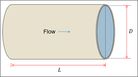
Hydraulic Shear Stress on the Surface of a Cylindrical Pipe
Figure: Flow through a cylindrical pipe.
Equation approximates the average hydraulic shear stress acting on the pipe by assuming static equilibrium.
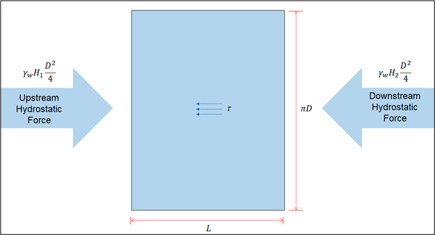
∑F=γWH14πD2−τ(πD)L−γWH24πD2=0
where:
F = force D = diameter of the pipe L = length of the pipe H1 = hydraulic head at upstream end of pipe (headwater elevation minus base of pipe elevation) H2 = hydraulic head at downstream end of pipe (tailwater elevation minus base of pipe elevation) γw = unit weight of water τ = average hydraulic shear stress
Figure: Free-body diagram for flow through a cylindrical pipe.
Solving for the average hydraulic shear stress results in Equation and Equation.
τ(πD)L=γW(H1−H2)4πD2
τ=4LγW(H1−H2)D
Equation calculates the average hydraulic gradient across the flow path.
i=LH1−H2
Therefore, Equation can be rewritten as Equation.
τ=4γWiD
Alternatively, the average hydraulic shear stress acting on the walls of the pipe can be approximated by a more general formula for the hydraulic
shear stress along a pipe as shown in Equation.
τ=γWiPwA
where:
A = average cross-sectional area of the flow
A=4πD2
where:
Pw = average wetted perimeter
Pw=πD
Substituting Equation, Equation, and Equation into Equation results in Equation, Equation, and Equation.
τ=γW(LH1−H2)πD(4πD2)
τ=4LγW(H1−H2)D
τ=4γWiD
Solving Equation for the pipe diameter and setting τ = τc (critical shear stress) results in the critical pipe diameter for initiation of concentrated leak erosion (Dcr) as shown in Equation, Equation, and Equation.
γW(H1−H2)D=4Lτc
Dcr=γW(H1−H2)4Lτc
Dcr=γW(H1−H2)4Lτc
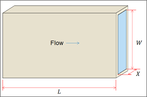
Hydraulic Shear Stress on the Surface of a Horizontal Crack
Figure: Flow through a horizontal crack.
Equation approximates the average hydraulic shear stress acting on the crack by assuming static equilibrium.
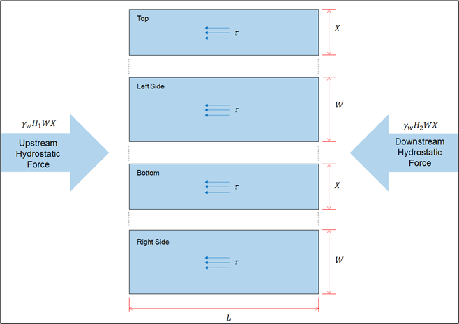
∑F=γWH1WX−τ(2WL+2XL)−γWH2WX=0
where:
F = force W = vertical crack dimension (crack width) X = horizontal crack dimension (crack width parallel to the embankment centerline) L = length of the crack H1 = hydraulic head at upstream end of crack (headwater elevation minus base of crack elevation) H2 = hydraulic head at downstream end of crack (tailwater elevation minus base of crack elevation) γw = unit weight of water τ = average hydraulic shear stress
Figure: Free-body diagram for flow through a horizontal crack.
Solving for the average hydraulic shear stress results in Equation and Equation.
τ(2WL+2XL)=γW(H1−H2)WX
τ=L(2W+2X)γW(H1−H2)WX
Equation calculates the average hydraulic gradient across the flow path.
i=LH1−H2
Therefore, Equation can be rewritten as Equation.
τ=2W+2XγWiWX
Alternatively, the average hydraulic shear stress acting on the walls of the crack can be approximated by a more general formula for the hydraulic
shear stress along a crack as shown in Equation.
τ=γWiPwA
where:
A = average cross-sectional area of the flow
A=WX
Pw = average wetted perimeter
Pw=2W+2X
Substituting Equation, Equation, and Equation into Equation results in Equation, Equation, and Equation.
τ=γW(LH1−H2)(2W+2XWX)
τ=L(2W+2X)γW(H1−H2)WX
τ=2W+2XγWiWX
Solving Equation for the crack width (vertical crack dimension) and setting τ = τc (critical shear stress) results in the critical crack width for initiation of concentrated leak erosion (Wcr) as shown in Equation to Equation.
Lτc(2W+2X)=γW(H1−H2)WX
Lτc(2W+2X)−γW(H1−H2)WX=0
2LτcW+2LτcX−γW(H1−H2)WX=0
W[2Lτc−γW(H1−H2)X]=−2LτcX
Wcr=2Lτc−γW(H1−H2)X−2LτcX
Wcr=2Lτc−γWiX−2τcX
Because W << X, the average hydraulic shear stress in Equation can be approximated as shown in Equation and Equation.
τ=2(0)+2XγWiWX
τ≈2γWiW
Solving Equation for the crack width and setting τ = τc (critical shear stress) results in the critical crack width for initiation of concentrated leak erosion as shown in Equation.
Wcr≈γWi2τc
Hydraulic Shear Stress on the Surface of a Vertical Rectangular Crack
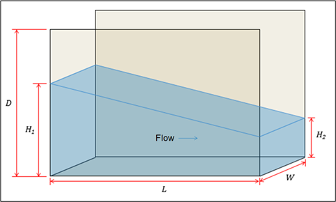
Figure: Flow through a vertical rectangular crack.
Equation approximates the average hydraulic shear stress acting on the crack by assuming static equilibrium.
∑F=21γWH12W−τ(2L(2H1+H2)+WL)−21γWH22W=0
where:
F = force D = depth of crack from top of core H1 = hydraulic head at upstream end of crack (headwater elevation minus base of crack elevation) H2 = hydraulic head at downstream end of crack (tailwater elevation minus base of crack elevation) L = equivalent length of crack for net hydraulic head W = width of crack at top of core γw = unit weight of water τ = average hydraulic shear stress
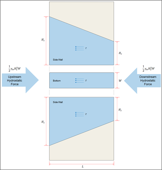
Figure: Free-body diagram for flow through a vertical rectangular crack.
Solving for the average hydraulic shear stress results in Equation and Equation.
τL(H1+H2+W)=21γWW(H12−H22)
τ=2L(H1+H2+W)γWW(H12−H22)
Alternatively, the average hydraulic shear stress acting on the walls of the crack can be approximated by a more general formula for the hydraulic
shear stress along a crack as shown in Equation.
τ=γWiPwA
where:
i = average hydraulic gradient across the flow path
i=LH1−H2
A = average cross-sectional area of the flow
A=21(WH1+WH2)
A=2W(H1+H2)
Pw = average wetted perimeter
Pw=21((2H1+W)+(2H2+W))
Pw=H1+H2+W
Substituting Equation, Equation, and Equation into Equation results in Equation and Equation.
τ=γW(LH1−H2)H1+H2+W2W(H1+H2)
τ=2L(H1+H2+W)γWW(H12−H22)
Solving Equation for the crack width at the top of the core and setting τ = τc (critical shear stress) results in the critical crack width for initiation of concentrated leak erosion (Wcr) as shown in Equation to Equation.
2Lτc(H1+H2+W)=γWW(H12−H22)
2Lτc(H1+H2)+2LτcW=γWW(H12−H22)
γWW(H12−H22)−2LτcW=2Lτc(H1+H2)
W(γW(H12−H22)−2Lτc)=2Lτc(H1+H2)
Wcr=γW(H12−H22)−2Lτc2Lτc(H1+H2)
Because H2 is often zero (i.e., no tailwater) and W << H1, the average hydraulic shear stress in Equation can be approximated as shown in Equation, Equation, and Equation.
τ≈2L(H1+0+0)γWW(H12−0)
τ≈2LγWWH1
τ≈2γWiW
Solving Equation for the crack width and setting τ = τc (critical shear stress) results in the critical crack width for initiation of concentrated leak erosion as shown in Equation.
Wcr≈γWi2τc
Hydraulic Shear Stress on the Surface of a Vertical Triangular Crack
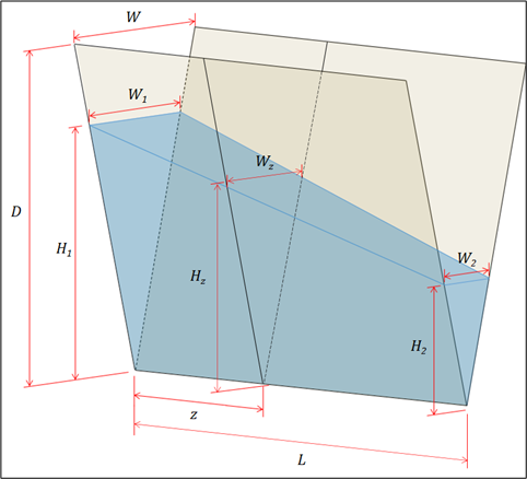
Figure: Flow through a vertical triangular crack.
Equation approximates the average hydraulic shear stress acting on the crack by assuming static equilibrium.
F = force D = depth of crack from top of core H1 = hydraulic head at upstream end of crack (headwater elevation minus base of crack elevation) H2 = hydraulic head at downstream end of crack (tailwater elevation minus base of crack elevation) Hz = height of water in crack at a distance z from upstream end of crack L = equivalent length of crack for net hydraulic head W = width of crack at top of core W1 = width of crack at upstream end of crack W2 = width of crack at downstream end of crack Wz = width of crack at a distance z from upstream end of crack Z = distance measured along base of crack from upstream end of crack γW = unit weight of water τ = average hydraulic shear stress
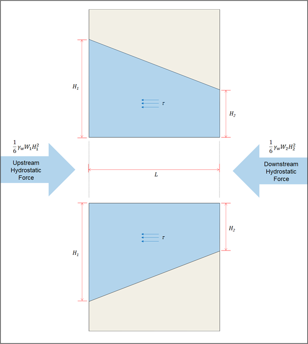
Figure: Free-body diagram for flow through a vertical triangular crack.
Solving for the average hydraulic shear stress results in Equation and Equation.
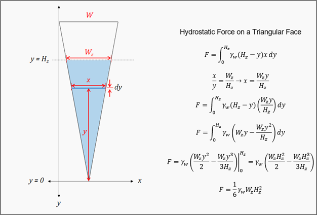
The derivation of the equation used to calculate the hydrostatic forces is shown in Figure A-9.
Figure: Hydrostatic force on a triangular face.
Alternatively, the average hydraulic shear stress acting on the walls of the crack can be approximated by a more general formula for the hydraulic
shear stress along a crack as shown in Equation.
τ=γWiPwA
where:
i = average hydraulic gradient across the flow path
i=LH1−H2
A = average cross-sectional area of the flow
A=L1∫0L21HzWzdz
where:
Hz = height of water in crack at a distance z from upstream end of crack Wz = width of crack at a distance z from upstream end of crack
Solving Equation for the crack width and setting τ = τc (critical shear stress) results in the critical crack width for initiation of concentrated leak erosion (Wcr) as shown in Equation to Equation.
Because H2 is often zero (i.e., no tailwater) and W << D, the average hydraulic shear stress in Equation can be approximated as shown in Equation, Equation, and Equation.
τ≈6DLγwW(H1+0)1+0(H13−0)
τ≈6DLγwWH12
τ≈6DγwiWH1
Solving Equation for the crack width and setting τ = τc (critical shear stress) results in the critical crack width for initiation of concentrated leak erosion as shown in Equation.