
Vertical Rectangular Crack
Method of Analysis
The method of analysis is the same as that described for the Cylindrical Pipe worksheet in the Method of Analysis section.
Critical Shear Stress and Initial Crack Dimensions
In step 2, input the critical shear stress for the embankment core and initial crack dimensions. The selections in step 1 affect the input for step 2, and cells that do not apply have a gray background. These cells are not used in subsequent calculations even if data is present.
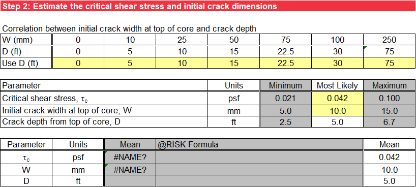
The first table in step 2 is the correlation between the initial crack width at the top of the core and the crack depth from the top of the core. The default values in the toolbox were adapted from Table 5.25 of Fell et al. (2008) [?] and are based on a review of the literature on observed cracking and the results of numerical modeling by Bui et al. (2005) [?]. A user-specified relationship can also be used. For transverse cracks or gaps adjacent to walls, use a constant depth for all crack widths.
For deterministic analysis, input only the most likely values. The mean value used for subsequent calculations is set equal to the most likely (or mode) value. Figure illustrates the deterministic input.
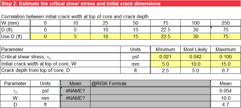
For probabilistic analysis without @RISK, input the minimum and maximum values in addition to the most likely value, and triangular distributions represent the random variables. The mean values used in subsequent calculations are the average of the minimum, most likely, and maximum values. Figure illustrates the probabilistic input without @RISK.
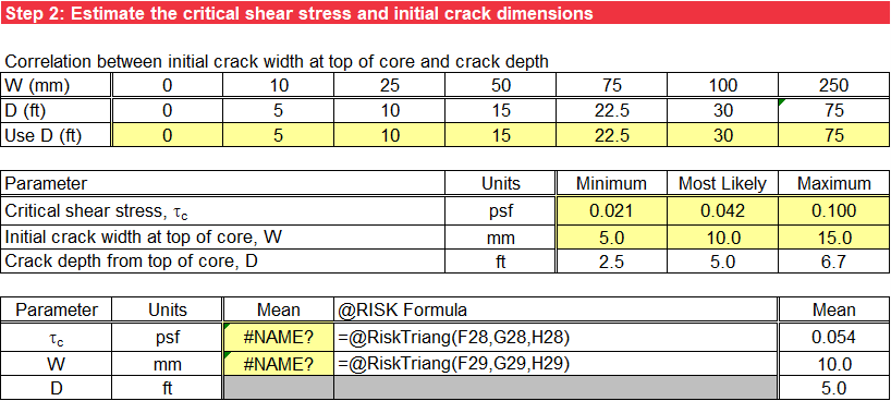
For probabilistic analysis using @RISK, input the minimum, most likely, and maximum values, and use an @RISK formula for a triangular distribution in the third column as a default. Alternatively, input a valid @RISK distribution in lieu of this default formula, and the user-specified input displays in the fourth column. The mean values used for subsequent calculations are the means for the @RISK distributions entered in the third column. Figure illustrates the probabilistic input using @RISK.
The RMC Erodibility Parameters Toolbox helps estimate the critical shear stress of the embankment core. The toolbox contains empirical relationships and published values based on field and laboratory testing. The RMC Concentrated Leak Erosion (Cracking) Toolbox helps estimate the initial crack dimensions for a variety of initiating mechanisms. Because it is very difficult to predict the depth and width of cracking, sensitivity analysis is recommended. Numerical modeling can also inform judgment.
The crack depths from the top of the core reported in the second and third tables are linearly interpolated from the correlation table defined at the beginning of step 2 using the initial crack width input.
Core Geometry
The core geometry is the same as that described for the Cylindrical Pipe worksheet in the Core Geometry section, but the base elevation of the crack is not an input because it is calculated by the toolbox from the step 2 input. Step 4 uses the slopes of the embankment core to calculate the equivalent length over which the hydraulic head difference occurs. Therefore, the lowest core elevation (minimum zbot) must be less than or equal to the lowest crack depth in step 2 to compute the length. A caution displays with an orange background if the minimum user-specified zbot for the upstream or downstream slope of the core is greater than lowest crack depth.
Hydraulic Shear Stress
Step 4 calculates the hydraulic shear stress on the surface of the vertical rectangular crack from flow of water in the crack using Equation.
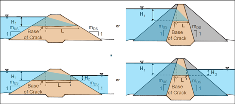
The length used in the calculation of the average hydraulic gradient across the core is the length of crack over which the net hydraulic head occurs and is referred to as the equivalent length. When there is no tailwater above the base of crack, the hydraulic head loss occurs over a length measured from the downstream face of the core at the base of the crack to a projection of the point where the headwater level intersects the upstream face of the core. When tailwater is above the base of crack elevation, the length is measured between the projection point where the headwater level intersects the upstream face of the core and the projection point where the tailwater intersects the downstream face of the core. Figure, adapted from Foster et al. (2002) [?], illustrates both hydraulic conditions for homogeneous embankments and zoned embankments where the upstream and downstream zones are very permeable (e.g., rockfill). Override the formula for equivalent length with a user-specified length for embankments with sloping cores, crack orientations that are not perpendicular to the embankment centerline, etc.
The hydraulic shear stress calculated at the bottom of the first table is for the mean crack width at the top of the core and the mean crack depth from the top of the core. Because some uncertainty is always present regarding the input parameters for this type of analysis, the second table reports the hydraulic shear stress using the same hydraulic conditions as the first table but for crack widths ranging from 1 millimeter to 150 millimeters. Because the crack depth is correlated to the crack width at the top of the core, supporting tables are also provided for hydraulic head at the upstream and downstream ends of the crack, equivalent length for net hydraulic head, and average hydraulic gradient across the core. The table of hydraulic shear stress as a function of crack width at the top of the core is used in step 6 to estimate the critical crack width.
Likelihood of Initiation of Concentrated Leak Erosion
The likelihood of initiation of concentrated leak erosion is the same as that described for the Cylindrical Pipe worksheet in the Likelihood of Initiation of Concentrated Leak Erosion section, but using a different equation and crack width instead of pipe diameter.
Headwater Level for Initiation of Concentrated Leak Erosion
The headwater level for initiation of concentrated leak erosion is the same as that described for the Cylindrical Pipe worksheet in the Headwater Level for Initiation of Concentrated Leak Erosion section, but using a different equation and crack width instead of pipe diameter.
Critical Crack Width for Initiation of Concentrated Leak Erosion
The critical crack width at the top of the core for initiation of concentrated leak erosion is the same as that described for the Cylindrical Pipe worksheet in the Critical Pipe Diameter for Initiation of Concentrated Leak Erosion section, but using a different equation and crack width instead of pipe diameter. Input the crack depth from the top of the core since the hydraulic head at the upstream and downstream ends of the core and equivalent length for net hydraulic head are functions of crack depth. Equation calculates the critical crack width at the top of the core for initiation of concentrated leak erosion for each headwater level and the specified crack depth from the top of the core.