Creep Ratios
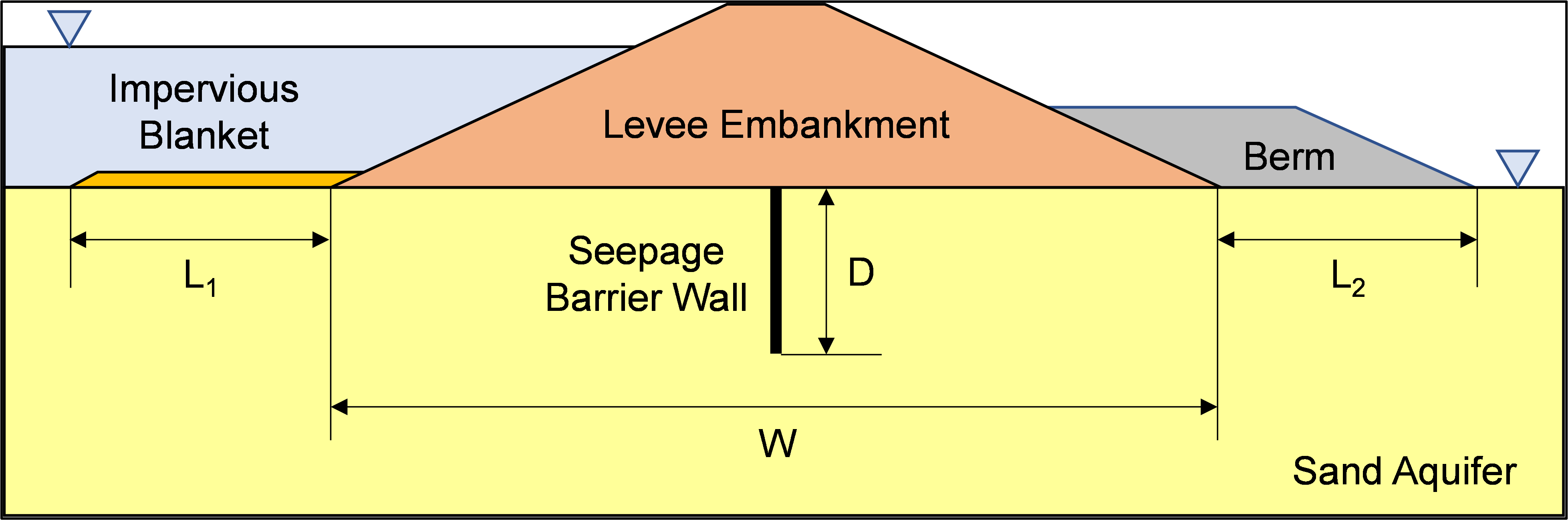
Creep ratio methods such as Bligh (1910) [?] and Lane (1935) [?] are empirical methods still used by some practitioners to assess the likelihood of BEP progression (hydraulic condition) based on observations of seepage performance for a range of soil types. Both empirical methods involve estimating the line of creep (or seepage path length) beneath concrete structures (such as weirs), including seepage barrier walls. For embankment dams and levees, the seepage path length includes the impervious embankment, as well as any upstream/floodside and downstream/landside impervious blankets or berms, seepage barrier walls, impervious foundation trenches, etc. as illustrated in Figure.
To assess the likelihood of BEP progression (hydraulic condition), the creep ratio for the headwater level under consideration is compared to the minimum (or safe) creep ratio for the piping material. The creep ratio is calculated as the line of creep (seepage path length) divided by the net hydraulic head. For Lane’s method, horizontal seepage path lengths are weighted three times less than the vertical seepage path lengths to account for the greater resistance to pipe development when a vertical structure (such as a seepage barrier wall) is present in the path of the pipe. Hence, it is often referred to as a weighted creep method. BEP progression is expected if the creep ratio is less than the minimum creep ratio.
Evaluating creep ratio is informative where the levee consists of fine-grained material and no landside blanket exists. The method is not appropriate for a compromised confining layer overlying a confined aquifer. Duncan et al. (2011) [?] state that while informative, the creep ratio is considered a “quick-and-dirty check.” The state of practice is to use rational methods based on blanket theory, flow nets, or finite-element method analysis, and the greatest remaining value of creep ratios lies in indicating the relative erosion potential of various soil types.
Line of Creep
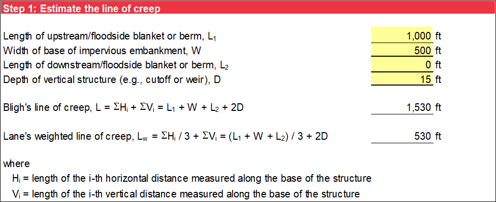
Step 1 calculates the line of creep (seepage path length) as illustrated in Figure. The input includes the horizontal impervious dimensions as well as the depth of any vertical structures (such as seepage barrier walls). The depth of vertical structures is doubled in the line-of-creep calculation because seepage must pass down, around, and up the embedded structure. If a blanket, berm, or vertical structure does not exist, input zero for those values.
The line of creep (L) for Bligh’s method is calculated using Equation. The weighted line of creep for Lane’s method (LW) is calculated using Equation.
Where:
D = depth (feet) of embedded vertical structure
L1 = length (feet) of upstream/floodside impervious blanket or berm
L2 = length (feet) of downstream/landside impervious blanket or berm
W = width (feet) of base of concrete weir or impervious embankment
Minimum Creep Ratio
Step 2 characterizes the foundation to obtain the minimum (or safe) creep ratio for both empirical methods from Lane (1935) [?] based on soil type as illustrated in Figure. Use the drop-down list to select the material that best represents the material along the piping path.
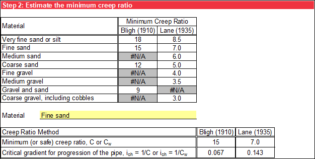
When seepage exits horizontally, piping can progress with an average horizontal gradient in the foundation as low as 0.05. This critical horizontal gradient is approximately the same as the inverse of Bligh’s creep ratio for fine sand. The field horizontal critical gradient for BEP progression (ich) is the inverse of the minimum (or safe) creep ratio if there are no vertical structures (D = 0). The field horizontal critical gradient is calculated using Equation and Equation for Bligh’s method and Lane’s method, respectively. For D greater than zero, “N/A” displays for ich.
Where:
Cmin = minimum (or safe) creep ratio for Bligh’s method
CW,min = minimum (or safe) weighted creep ratio for Lane’s method
Creep Ratio
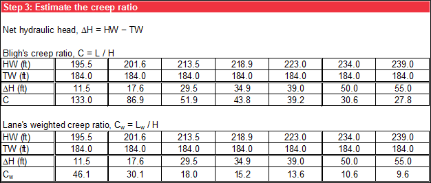
Step 3 calculates the creep ratio by dividing the line of creep from step 1 by the net hydraulic head (ΔH) for the headwater level under consideration. The creep ratio for Bligh’s method (C) is calculated using Equation. The weighted creep ratio for Lane’s method (CW) is calculated using Equation.
Where:
ΔH = net hydraulic head (feet)
HW = headwater level (feet)
TW = tailwater level (feet)
L = line of creep for Bligh’s method (feet)
LW = line of creep for Lane’s method (feet)
The calculated creep ratio is compared to the minimum creep ratio from step 2, and cells where the calculated creep ratio exceeds the minimum value have an orange background. Figure illustrates the tabular summary.
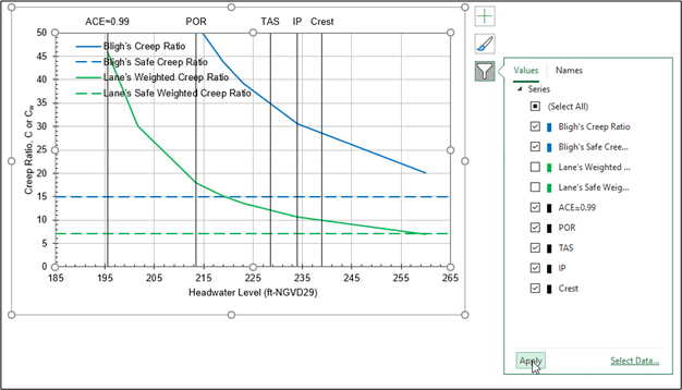
The calculated creep ratio is plotted as a function of headwater level for both methods. Horizontal reference lines display the minimum (or safe) creep ratios for each method. Figure illustrates the graphical output. The legend can be moved within the plot area as necessary for clarity.
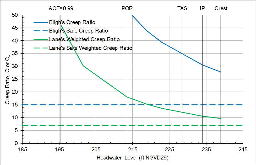
Figure illustrates the plot options for this chart. The maximum value for the y-axis (creep ratio) and minimum and maximum values for the x-axis (headwater level) are user-specified. Users can input up to five vertical reference elevations, and user-specified labels displayed at the top of the chart.
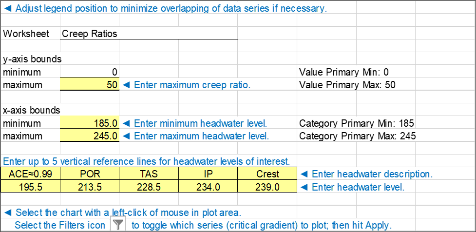
By selecting the chart and then selecting the filter icon to display the filter pane, the data series for display can be selected as illustrated in Figure. For example, if only the results from the Bligh’s method are judged applicable, the data series for “Lane’s Weighted Creep Ratio” and “Lane’s Safe Weighted Creep Ratio” can be deselected so that they do not plot or display in the legend.