Sinkhole
This worksheet assesses the stability of residual soil as a function of potential soil void diameter to assess the impact of a sinkhole developing at a given location on the of likelihood of breach. Drumm et al. (2009) [?] developed a dimensionless stability chart to evaluate the stability of residual soils in karst where subsurface voids may exist near the rock contact and collapse of these voids may result in a sinkhole.
The sinkhole size and location and impounded water level at the time of the sinkhole are critical to evaluating the likelihood of breach due to sinkhole development. If the sinkhole occurs near the embankment crest with an elevated water level, it may lower the crest quickly and lead to overtopping with breach. If the sinkhole occurs downstream of the embankment centerline, progressive instability is needed to eventually cause loss of freeboard, but for this scenario, there is usually sufficient time for intervention and corrective action.
Figure shows the idealized profile from Drumm et al. (2009) [?] with residual soil thickness (h) above a subsurface void of diameter (D) overlying bedrock. A weak zone of thickness overlying the rock surface is also shown in the figure, which is discussed in Undrained Stability (Short-Term Conditions).
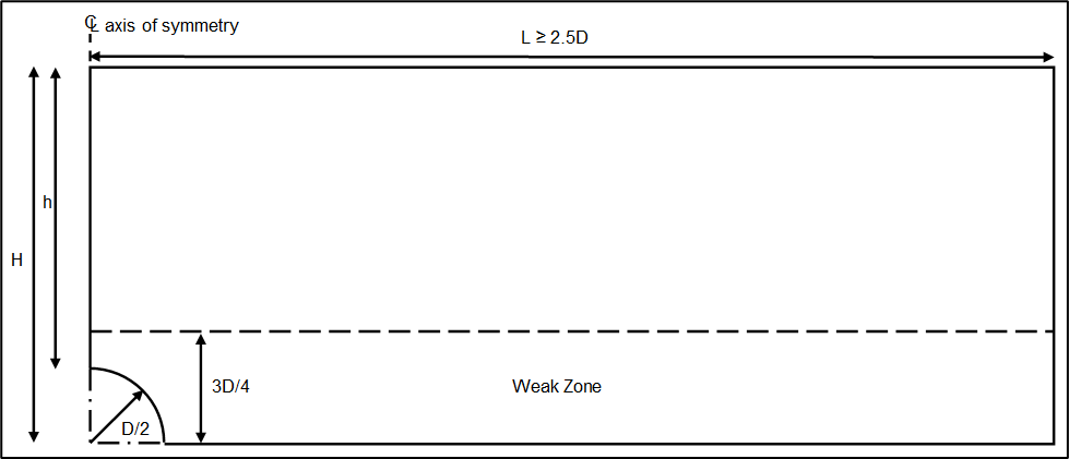
The thickness (h) of the residual soil above the void at the rock surface is calculated using Equation.
where:
H = embankment height above the rock contact
D = void diameter
Assuming no internal cavity pressure, the methodology compares a dimensionless stability number for a spherical void in residual soil overlying the rock surface for undrained (short-term) and drained (long-term) conditions to a critical dimensionless stability number. From the results of the numerical analyses, critical stability numbers were developed for different strength and geometric conditions as shown in Figure.
![[object Object]](/RMC-Software-Documentation/figures\toolbox-technical-manuals\internal-erosion-suite\breach\v1.0\figures\figure22.png)
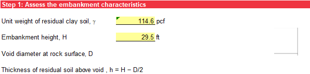
Embankment Characterization
Step 1 characterizes the embankment. Input the unit weight of the residual clay soil and the height of the embankment as shown in Figure.
Undrained Stability (Short-Term Conditions)
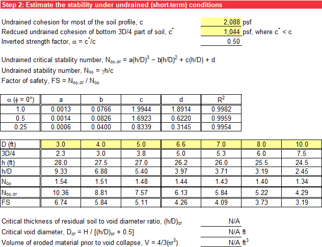
Step 2 assesses the stability of residual soils in karst, where subsurface voids may exist near the rock surface, under undrained (short-term) conditions. Soils in karst often show a shear strength profile that decreases at depths near the rock contact, commonly known as an inverted residual soil strength profile. To account for the reduction in shear strength, the evaluation of undrained conditions includes a reduced cohesion value (c*) for a weak zone overlying rock with a thickness of .
Input the undrained cohesion (c) of the residual soil above the weak zone and the reduced cohesion of the weak zone above the rock surface (c*) with thickness , as shown in Figure.
The dimensionless stability number (Ncφ) for undrained (short-term) conditions is calculated using Equation.
where:
γ = unit weight of the residual clay soil
h = soil thickness above the void
c = undrained cohesion
The critical dimensionless stability number for undrained (short-term) conditions as a function of is portrayed as a stability chart in Figure and is calculated using Equation.
where:
a, b, c, and d = constants (see Table)
= ratio of the thickness of the residual soil above the void at the rock surface to void diameter
To account for the inverted residual soil strength profile in the stability chart, [?] also evaluated a weak zone of thickness overlying the rock surface with a reduced cohesion value (c*). The inverted strength factor (α) relating to the two cohesion values is calculated using Equation.
where:
c = undrained cohesion for the soil above the weak zone
c* = reduced cohesion for the soil in the weak zone
The values of the constants for undrained (short-term) conditions are shown in Table for values of a equal to 0.25, 0.5, and 1.0 and undrained angle of internal friction (φ) equal to zero. Intermediate values are linearly interpolated.
| a | B | C | D | ||
|---|---|---|---|---|---|
| 1.0 | 0.0013 | 0.0766 | 1.9944 | 1.8914 | 0.9982 |
| 0.5 | 0.0014 | 0.0826 | 1.6923 | 0.6220 | 0.9959 |
| 0.25 | 0.0006 | 0.0400 | 0.8339 | 0.3145 | 0.9954 |
When is greater than , the void is predicted to be unstable, and a sinkhole is likely to form. The factor of safety (FScφ) against undrained instability is calculated using Equation.
Input (in ascending order) up to seven different void diameters as shown in Figure. If the void radius () exceeds the embankment height (H) input in step 1, the void diameter cells have an orange background. Cells with FS less than 1 have an orange background. The critical thickness of residual soil to void diameter ratio is linearly interpolated for a FS of 1. If possible, provide a sufficient range of void diameters to result in at least one computed FS greater than 1 and one less than 1, to calculate .
Solving Equation for the void diameter (D) yields Equation.
Substituting for in the denominator of Equation, the critical void diameter (Dcr) is calculated using Equation.
The volume of eroded soil prior to void collapse (V), assuming a spherical void, is calculated using Equation.
The radius (r) in Equation is calculated using Equation:
If the range of user-specified diameters of the void above the rock contact is not sufficient to interpolate a FS of 1, N/A is displayed for , Dcr, and V. The undrained (short-term) stability evaluation is illustrated in Figure.
Drained Stability (Long-Term Conditions)
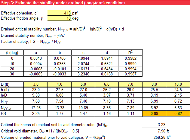
Step 3 assesses the stability of residual soils in karst, where subsurface voids may exist near the rock surface, under drained (long-term) conditions. Input the effective cohesion (c′) and the effective angle of internal friction (φ′) of the residual clay soil as shown in Figure.
The dimensionless stability number (Nc'φ') for drained (long-term) conditions is calculated using Equation.
where:
γ = unit weight of the residual clay soil
h = soil thickness above the void
c′ = effective (drained) cohesion
The critical dimensionless stability number for drained (long-term) conditions as a function of is portrayed as a stability chart in Figure and is calculated using Equation.
where:
a, b, c, and d = constants (see Table)
= ratio of the thickness of the residual soil above the void at the rock surface to void diameter
The values of the constants for drained (long-term) conditions are shown in Table for various values of effective (drained) angle of internal angle (φ'). Intermediate values are linearly interpolated.
| ɸ′ (deg) | A | B | C | d | |
|---|---|---|---|---|---|
| 0 | 0.0013 | 0.0766 | 1.9944 | 1.8914 | 0.9982 |
| 10 | 0.0004 | 0.0353 | 2.0744 | 0.6521 | 0.9990 |
| 20 | -0.0008 | -0.0101 | 2.6131 | 0.6484 | 0.9994 |
| 30 | -0.0005 | -0.0033 | 3.2346 | 0.6168 | 0.9987 |
When Nc'φ' is greater than Nc'φ',cr, the void is predicted to be unstable, and a sinkhole is likely to form. The FS against drained instability (FSc'φ') is calculated using Equation.
Input (in ascending order) up to seven different void diameters as shown in Figure. If the void radius () exceeds the embankment height (H) input in step 1, the void diameter cells have an orange background. Cells with FS less than 1 have an orange background. The critical thickness of residual soil to void diameter ratio is linearly interpolated for a FS of 1. If possible, provide a sufficient range of void diameters to result in at least one computed FS greater than 1 and one less than 1, to calculate . The volume of eroded soil prior to void collapse (V) is calculated the same as in undrained (short-term) conditions. The drained (long-term) stability evaluation is illustrated in Figure.
Summary
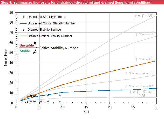
In step 4, the stability numbers for undrained (short-term) conditions (blue circles) and drained (long-term) conditions (red circle) are plotted as a function of at the bottom of the worksheet, as shown in Figure. Reference lines for the critical stability number for undrained (short-term) conditions (blue line) and drained (long-term) conditions (red line) are also plotted as a function of . When a stability number plots above the reference line, the void is predicted to be unstable, and a sinkhole is likely to form. The light gray lines provide the critical stability numbers for the undrained and drained conditions modeled by Drumm et al. (2009) [?] for reference.